1749
Technical Committee 204 /
Comité technique 204
0
30
60
90
120
150
180
0
2
4
6
8
1
v
(kPa)
h
(m)
0
overburden
90°
80°
70°
60°
50°
40°
30°
20°
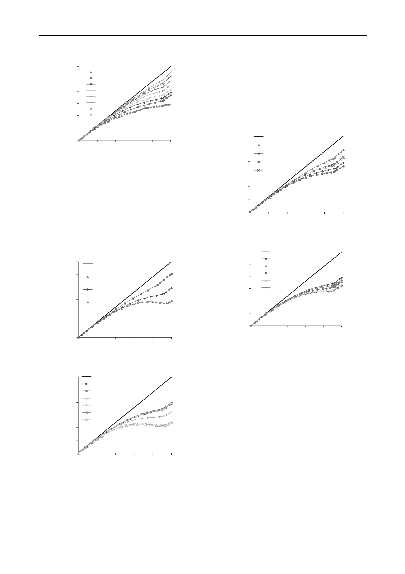
Figure 4. Vertical stress variation along the VCL of the trench for
different wall inclination angle
; other parameters are given in Table 1.
3.2
Effect of backfill properties
3.2.1
Cohesion
Figure 6 shows the vertical stress distributions obtained by
numerical simulations along the VCL for different values of the
backfill cohesion
c
'
b
. These results tend to indicate that the
stress magnitude may change significantly with the cohesion
within the interval between 1 kPa and 100 kPa. Below a value
of 1 kPa, the effect of cohesion can be considered negligible;
once the backfill cohesion value reaches 100 kPa, further
increase does not have any effect on the vertical stress
distribution (in the cases considered here).
0
30
60
90
120
150
180
0
2
4
6
8
1
v
(kPa)
h
(m)
0
overburden
1 m
2 m
4 m
Figure 5. Vertical stress distribution along the VCL for different width
at the base of the trench (
L
b
); details are given in Table 1.
0
30
60
90
120
150
180
0
2
4
6
8
1
v
(kPa)
h
(m)
0
overburden
0 kPa
0.1 kPa
1 kPa
10 kPa
100 kPa
1 000 kPa
Figure 6. Vertical stress distribution along the VCL for different backfill
cohesion
c
'
b
; details are given in Table 1.
3.2.2
Internal friction angle
Figure 7 presents the vertical stress distributions along the VCL
with the trench. These simulations results indicate that a
stronger backfill, with a higher friction angle
'
b
, induces more
stress transfer to the walls, due to arching effect, so the vertical
stresses are reduced.
It is worth noting here that these results are somewhat
different from those obtained for vertical and inclined backfilled
mine stopes, where the vertical stresses becomes almost
insensitive to
'
b
when the friction angle is greater than about
20° (e.g. Li and Aubertin 2009c; Singh et al. 2010).
3.2.3
Dilation angle
Figure 8 illustrates the vertical stress distribution along the VCL
in the trench, obtained for different backfill dilation angle
'
b
.
Results tend to indicate that the stress magnitude tends to
decrease slightly when the dilation angle increases from 0° to
30°.
0
30
60
90
120
150
180
0
2
4
6
8
1
v
(kPa)
h
(m)
0
overburden
10°
30°
40°
20°
Figure 7. Vertical stress distribution along the VCL for different backfill
friction angle
'
b
; details are given in Table 1.
0
30
60
90
120
150
180
0
2
4
6
8
1
v
(kPa)
h
(m)
0
overburden
0°
5°
10°
20°
30°
Figure 8. Vertical stress distribution along the VCL for different backfill
dilation angle
'
b
; details are given in Table 1.
3.2.4
Young's modulus
The influence of the backfill stiffness on the vertical stress
distribution along the VCL is presented in Figure 9. It is
observed that the vertical stress is almost constant when the
value of the Young's modulus of the backfill is smaller than
about 1/30
th
of that of the material forming the walls. Beyond
that value, the vertical stress can increase significantly with an
increase in backfill stiffness.
It is also seen that the vertical stress magnitude is always
below the linear overburden solution, even when the backfill is
stiffer than the wall, indicating that there is no negative arching
in these cases. This response is due to the fact that the
settlement of the soil adjacent to the trench takes place before
the fill is put in place. This differs from results predicted by
some conventional solutions.
3.2.5
Poisson's ratio
The influence of the Poisson's ratio of the backfill on the
vertical stress distribution along the VCL is presented in Figure
10. One sees that the influence of this parameter on the vertical
stress distribution is very limited. This observation is quite
different from that for inclined mine backfilled stope where the
vertical stress decreases significantly with an increase in
backfill Poisson's ratio (Li and Aubertin 2009c).


