1745
Technical Committee 204 /
Comité technique 204
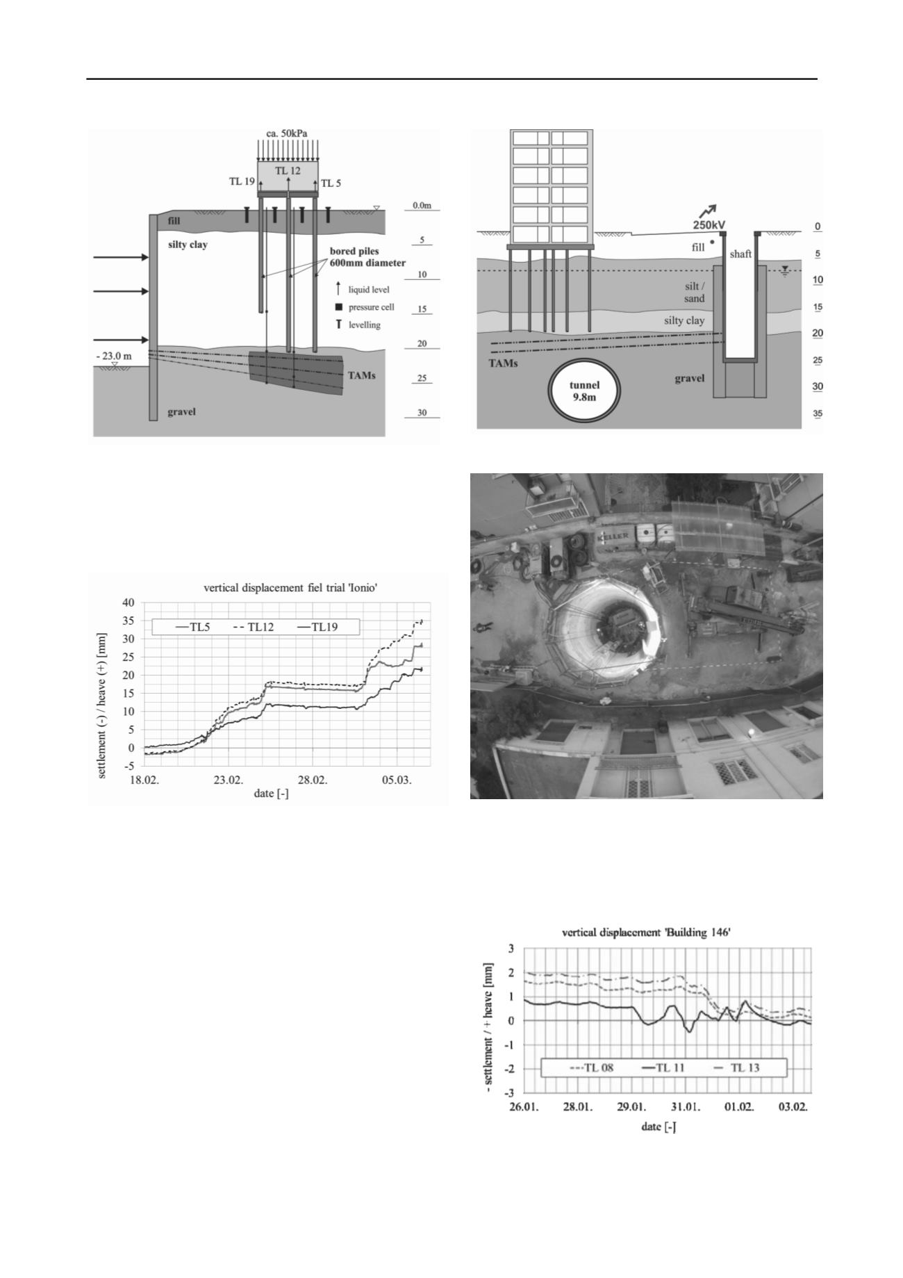
Figure 6. Field trial for real-scale testing of the response of grouting
underneath piled foundations.
Due to the high void content of the soil a considerable grout
take was observed during the pre-treatment phase. The targeted
heave of 20 mm was achieved with grout efficiencies
comparable to those with shallow foundations. The results can
be seen in Fig. 7 for selected water levels.
Figure 7. Vertical heave of selected pile heads monitored during the
heaving phase.
With the results obtained from the field trial the protection of
4 buildings was designed. For the TAM arrays two deep shafts
were realized in closest vicinity to service lines such as a high
voltage power line and adjacent apartment buildings (see Figs. 8
and 9). For the shaft construction Soilcrete-jet grouting was
utilized for the lateral walls (two rows of columns) and the
sealing slab as it proved to be a flexible and reliable solution.
Buildings were monitored with real-time monitoring during jet
grouting. The control of the jet grouting elements and the water
tightness of the shaft was performed by means of pumping tests
and thermal leakage and diameter controls.
From the shafts (max. 24 m deep, inner diameter 5.0 m and
6.0 m, respectively) two layers of TAMs at a maximum depth of
approx. 20 m were installed without disturbance of the adjacent
structures. Due to the variable pile length, TAMs were
implemented at different depths in order to keep the distance
between TAMs and piles constantly at 1.0 to 1.5 m.
Figure 8. Schematic cross section of piled foundation at ‘Ionio Station’.
Figure 9. Arial view of finished shaft with 6 m inner diameter and 24 m
depth.
The deformation of ’Building 146’ is represented in Fig. 10.
Generally the passive effect of the pre-treatment phase reduced
the deformation, with active grouting an additional reduction of
absolute and differential settlement was obtained.
Figure 10. Vertical response of buildings during TBM excavation.


