1738
Proceedings of the 18
th
International Conference on Soil Mechanics and Geotechnical Engineering, Paris 2013
Proceedings of the 18
th
International Conference on Soil Mechanics and Geotechnical Engineering, Paris 2013
-70
-60
-50
-40
-30
-20
-10
0
L1N2終了 N3終了 L2M 2終了 M 3N4終了 M 4N5終了 M 5終了 M 6N6終了 M 7O2終了
L1l2 N3 L M2 M3N4 M4N5 M5 M6N6 M7O2
Advanced box-modules No.
Vertical displacement (mm)
Calculated
Measured
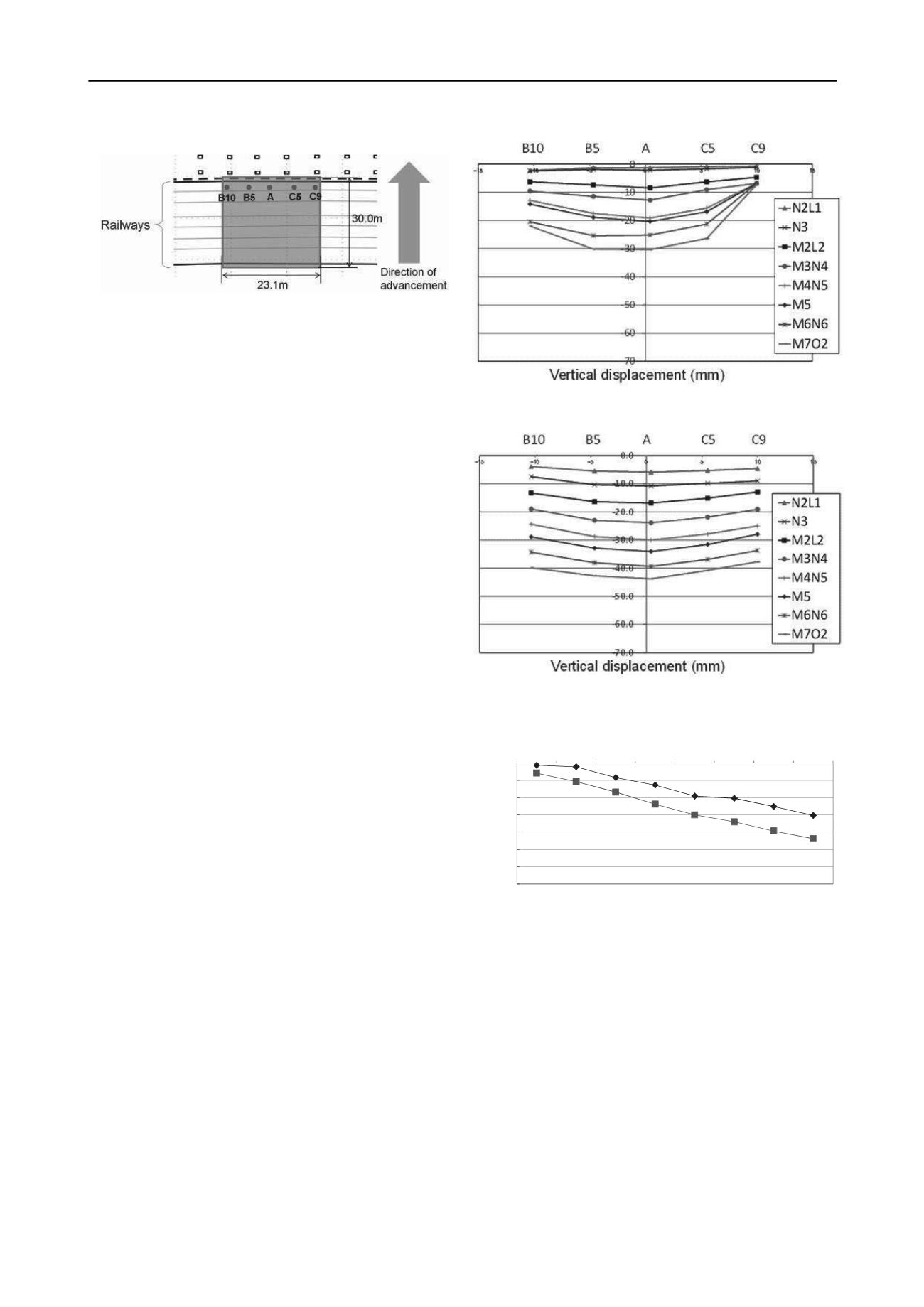
Figure 8. Location of the measurement points.
advancement of box-modules L1, L2 and L3, both the
calculated and measured vertical displacements are almost
identical after the insertion of the L3.
4 CONCLUSIONS
In this paper, the advancement and excavation processes of the
new modular approached tunnelling method were modelled
using the finite element method in order to investigate the effect
of these construction processes on the ground response. The
excavating finite element introduced in front of the cutting face
of the tunnel boring machine, and the operation of box-module
advancement and of soil excavation was simulated using the
finite element remeshing technique at each time step of the
analysis. The proposed modelling techniques were applied to
simulate a modular approached tunnelling work in soft ground
in Tokyo and the results were compared with the field
measurements.
The vertical displacement profiles of the lining frame were
obtained from the three-dimensional finite element simulation
using the proposed modelling technique for nine insert sections
of the box-module.
The shape of the computed settlement trough at the top of the
lining frame was similar to the measured results. Although the
calculated magnitude of vertical displacement was larger than
those in the first two insert sections, both the calculated and
measured vertical displacements of the lining frame were almost
identical after the third insert section of the box-module.
5 REFERENCES
Goodman,R.E., et.al. (1968) A Model for the Mechanics of
Jointed Rock, Proc. ASCE, Vol.94, No.SM3, pp.637-659
Nozawa, S. 2003. Reduction of the cost of construction in the
space above and below rails,
JR EAST Technical Review
,
East Japan Railway Company, 4, 23-28.
K. Komiya, et.al. 1999. Finite element modelling of excavation
and advancement processes of a shield tunnelling machine,
Soils and Foundations
, Japanese Geotechnical Society,
39(4), 37-52.
Figure 9. Measured vertical settlement trough on the top part of
the existing lining frame.
Figure 10. Calculated vertical settlement trough on the top part of the
existing lining frame.
Figure 11. Vertical displacement against the order of the box-module
constructions.


