1733
Technical Committee 204 /
Comité technique 204
q 2 5 γ αD p
36864α
M
18432α
M
A √3k4M
9192α
M
4M
9
(14)
where
A
and
k
are as defined in equations 9b and c,
respectively. By substituting values of parameters in Eq. 14, it is
possible to calculate a uniform upward pressure
q
to get a trap
door stable for a provided failure mode.
2.5 Estimation of a most critical configuration of a
loosened zone and supporting pressure q*
To estimate a most critical size of a loosened zone, a maximum
value of
q
with respect to a shape parameter
α
should be
calculated. This calculated
q
is a necessary uniform upward
pressure to support a trap door q*, provided that a failure
mechanism of the above soil is assumed to be a parabola. In this
paper, these calculations of q* are carried out for various
combinations of soil parameters.
Finally, calculated quantities such as a most critical size
parameter
α
and a most critical uniform upward pressure q* are
summarized as a function of soil parameters
M , p
and a width
of a trap door D.
3 ANALYTICAL RESULTS AND DISCUSSIONS
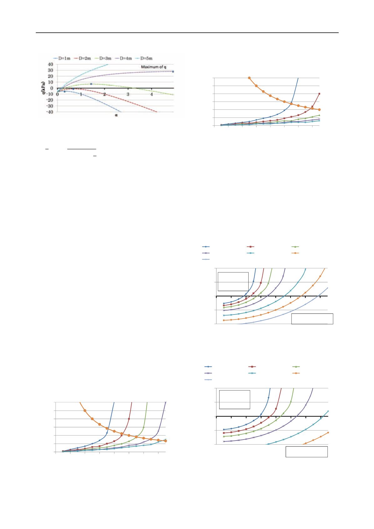
Figure 4 illustrates a relation of a loosened zone size parameter
a and a uniform upward pressure q to support a trap door with
various trap door width D cases for a given soil condition. A
largest (critical) value of q for each case is denoted as solid
circle. For cases of a trap door width D=1m and D=2m, critical
values of q* are negative. This indicates that a trap door is
stable without a upward supporting pressure. In opposite to this,
for cases of D=3m and 4m cases, upward supporting pressures
are necessary to keep a trap door stable. In addition to this, for a
case of D=5m, a largest value of q cannot be found within a
range of a between 0 and 5. There results directly means that
stability of a trap door is deteriorated if a width of a trap door is
larger. It is commonly observed in tunneling engineering that a
pilot tunnel or a bench excavation is adopted prior to a full cross
section excavation.
Figure 5 depicts a relation of a size of a loosened soil
α
and
a trap door width D at a critical supporting pressure q*. In this
example, soil parameters are assumed that a maximum
consolidation stress is 200 kPa and various internal friction
angles. In this figure, a limit of the assumed failure modes is
also drawn such that d =
α
* D under the assumption that a
depth of a soil layer is d=20m. This limit line coincides with
cases when a loosened zone reaches the surface of a ground. For
such cases, a ground arch action cannot be expected. Figure 6 is
also a relation of a size parameter and a trap door width for
p
y
’=300 kPa cases.
Figure 4.Relation of uniform supporting pressure q and a size
parameter of a loosened zone
α
(M=0.772 [
φ
=20 deg.], p
y
’ = 100kPa)
Figure 6.Relation of a trap door width D and a size parameter of a
loosened zone
α
(p
y
’ = 300kPa, buried depth 20m [assumption])
0
1
2
3
4
5
6
0 2 4 6 8 10 12 14
α
D(m)
φ
=20 deg.
25 deg.
30 deg.
35 deg.
40 deg.
A loosened
zone emerges
on a surface
Figure 7.Relation of a trap door width D and a upward supporting
pressure q for various consolidation stress cases
(p
y
’ = 80-300kPa,
internal friction angle
φ
=30 deg.)
-40
-20
0
20
40
0 2 4 6 8 10 12 14
q(kPa) k
D(m)
py'=80kPa
py'=100kPa py'=120kPa
py'=150kPa py'=200kPa py'=250kPa
py'=300kPa
Unstable
(q < 0)
Stable (q > 0)
Figure 5.Relation of a trap door width D and a size parameter of a
loosened zone
α
(p
y
’ = 200kPa, buried depth 20m[assumption])
0
1
2
3
4
5
6
0 2 4 6 8 10 12 14
α
D(m)
φ
=20 deg. 25 deg.
30 deg.
35 deg.
40 deg.
A loosened
zone emerges
on a surface
Figure 8.Relation of a trap door width D and a upward supporting
pressure q for various consolidation stress cases
(p ’ = 80-300kPa,
Stable (q > 0)
Unstable
(q < 0)
-40
-20
0
20
40
0 2 4 6 8 10 12 14
q(kPa)
D(m)
py'=80kPa py'=100kPa py'=120kPa
py'=150kPa py'=200kPa py'=250kPa
py'=300kPa


