1725
Technical Committee 204 /
Comité technique 204
where
S
v
max
is the maximum surface settlement (along the axis of
the tunnel),
x
is the distance from the axis of the tunnel along
the horizontal, and
l
x
is the argument of the inflection point on
the settlement curve.
S
and
l
are parameters obtained in
accordance with the method of Peck (1969) and others.
The correction factors are varied from 1 to 2.5 relative
embedment depths of the shallow tunnel.
3 GROUND-SURFACE SETTLEMENTS IN MOSCOW
Soils of different origin and age reside in the Moscow area.
Analysis of cores taken by the Mosgorgeotrest has made it
possible to isolate seven typical geologic-engineering sections
in the area (
Moscow City Building Code 2-07-97
).
Average physico-mechanical characteristics of the soils in
the sections described were presented (Ilyichev et al 2009).
Settlement (a), relative nonuniformity (b), and surface-
curvature (c) plots of seven characteristic geologic-engineering
sections of Moscow were constructed (using the method of
surface-settlement prediction) (Fig. 4) for analysis of surface
deformations.
Maximum surface settlements (5-120 mm) and the width of
the zone of influence
B
zi
(where it is necessary to conduct
geotechnical monitoring) were determined as a function of the
depth
z
0
of the longitudinal axis of the tunnel (Table 2).
Table 2.Width of the zone of influence
B
zi
.
Types of geologic-engineering
conditions
½ B
zi
I
2.0
z
0
II
1.5
z
0
III
1.5
z
0
IV
2.5
z
0
V
1.5
z
0
VI
2.5
z
0
VII
1.2
z
0
a)
b)
c)
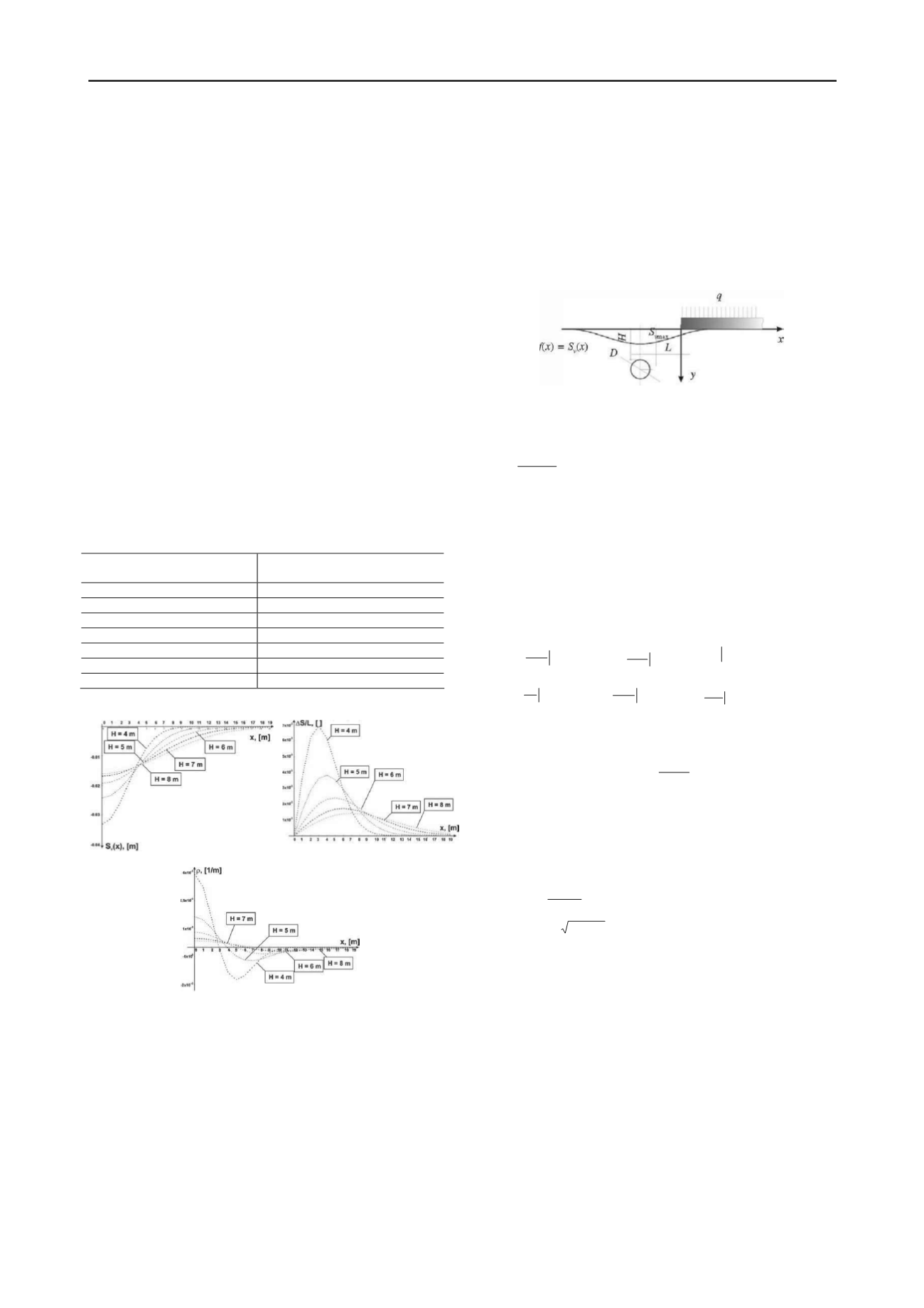
Figure 4.
Plots showing settlement (a), relative nonuniformity of surface
settlement (b), and surface curvature (c) during opening of shallow
utility tunnels for first type of geologic-engineering conditions in
Moscow (
D
= 4 m;
V
L
= 2%): 1-5)
H
= 4-8 m, respectively.
4 PREDICTION OF BUILDING SETTLEMENTS DURING
OPENING OF SHALLOW TUNNELS
To calculate the settlements of buildings during the opening of a
shallow utility tunnel, it is necessary to determine the weight of
the building, its stiffness, the distance from the apex of the
utility tunnel, the depth and diameter of the tunnel, and the
deformability of the soil. For this purpose, we have solved the
problem of a beam on an elastic Winkler bed with an assigned
support-line displacement, which is described by the formula
for vertical displacement based on the method of surface-
settlement prediction of a soil.
A building situated transversally in plan to the route of the
utility tunnel was modeled by a beam of infinite (the building is
situated above the route of the tunnel) and semi-infinite length
(the building is situated at a certain distance along the surface of
the ground from the axis of the tunnel, Fig. 5).
Nikiforova(2008) has proposed and taken a similar approach to
prediction of building deformations within the zone of influence
of deep trenches.
Figure 5.Mutual position of beam of semi-infinite length, and shallow
utility tunnel with assigned support-line displacement
f
(
x
).
The differential equation of the beam's deflections
)x(f k )x(q )x(yk
dx
)x(ydEJ
4
4
(3)
where
EJ
is the bending stiffness of the beam,
k
is the
coefficient of subgrade reaction of the bed,
q
(
x
) is the load on
the beam, and
f
(
x
) is the assigned displacement of the lines of
the beam's elastic support.
B. G. Korenev's (1954) method can be employed to solve the
problem of a beam on an elastic bed under an arbitrarily
distributed load using an influence function for the displacement
of the beam due to a concentrated force.
The boundary conditions of the semi-infinite beam loaded by
a concentrated force
P
on the left end:
P
dx
ydEJ
x
0 3
3
,
0
0 2
2
x
dx
ydEJ
,
0
x
)x(y
,
0
x
dx
dy EJ
,
0
2
2
x
dx
ydEJ
,
0
3
3
x
dx
ydEJ
(4)
In formula (3),
f
(
x
) is the vertical displacement of the surface
in accordance with the method of predicting surface settlement
during construction of shallow utility tunnels
,
) (
)(
)(
2
2
2
2
) (
max
1
x
l
x
C
v
v
e
S C xS xf
(5)
where
C
1
and
C
2
are coefficients, as defined by formulas (1),
S
v
max
is the maximum vertical displacement, and
l
x
is the distance
to the inflection point on the surface-settlement diagram.
According to Korenev(1954), solution of the bending
problem for infinite and semi-infinite beams assumes the form,
respectively:
x cos
e
EJ
P )x(y
x
II
3
2
,
(6)
where
4
4
EJ /k
.
Let us rewrite (6) as
)x(KP )x(y
i
(7)
where
K
i
(
x
) is the line of influence of the load
P
on the
deflection of the beam.
For an arbitrary load
p
(ξ), the expression for the deflections
,
(8)
d) x(K) (p )x(y
i
0
In the case where beam deflections are caused by the
construction of a shallow utility tunnel, expression (8) will take
on the form of (9) for a semi-infinite beam
,
(9)
d) x(K)Lx(f k )x(y
i
II
0
Thus, the problem of the beam's deflection reduces to
calculation of integrals (9).
The expressions derived for the deflections of the infinite
and semi-infinite beams assume the forms, respectively


