1718
Proceedings of the 18
th
International Conference on Soil Mechanics and Geotechnical Engineering, Paris 2013
9 DYNAMIC ANALYSIS RESULTS - AXIAL FORCE
AND JOINT DEFORMATHON OF THE TUNNEL
STRUCTURE
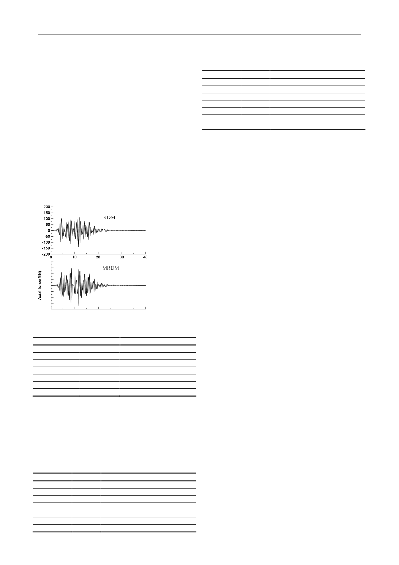
In this paper, the initial values of internal force and deformation
of the tunnel under static loads have been removed from the
final analysis results. The time history of axial force at location
A is shown in Fig. 8 using the response displacement method
(RDM) and modified response displacement method (MRDM),
respectively. Moreover, peak values of the axial forces in seven
different positions are given in Table 2. It can be seen that the
values of axial force at both sides of the tunnel are much larger
than those in the middle of the tunnel despite anyone of the two
approaches, therefore the soil foundation at both sides of the
tunnel should be reinforced for resisting the earthquake loading.
It is also readily seen that the computed results using MRDM
are larger than that using RDM, which means that inertia of the
tunnel plays such an important role in the seismic response of
the tunnel that it cannot be neglected. Therefore, it is suggested
that the purely dynamic analysis method, i.e., MRDM, should
be employed for seismic design of immersed tunnels.
Figure 8. Time history of axial force at location A
Table 2: Axial force of segments in different positions (MN)
Location
RDM
MRDM
A
138.80
173.30
B
28.55
111.70
C
37.73
74.70
D
9.32
20.88
E
41.34
79.91
F
35.66
72.05
G
98.97
96.34
Table 3 and Table 4 show the net maximum tension and
compression of GINA joints under seismic loading. It can be
seen that the values of deformations of joints at both sides of the
tunnel are much larger than those in the middle of the tunnel in
the two approaches, which is analogous to that of the axial force.
Moreover, it is concluded that excessive tension and
compression will not occur under proper design of segment
joints, which is not discussed here in detail in view of the space
limitation.
Table 3: Maximum tension of joints in different positions (mm)
Location
RDM
MRDM
E31\E30
-8.2
-13.0
E27\E26
-3.3
-6.6
E22\E21
-2.0
-4.4
E17\E16
-1.0
-2.9
E11\E10
-3.4
-7.3
E6\E5
-0.5
-1.3
E2\E1
-10.8
-12.7
Table 4: Maximum compression of joints in different positions (mm)
Location
RDM
MRDM
E31\E30
8.4
14.1
E27\E26
2.8
5.3
E22\E21
2.1
3.7
E17\E16
1.1
2.9
E11\E10
3.4
7.0
E6\E5
0.5
1.3
E2\E1
10.4
12.9
10 CONCLUSIONS
At the basis of the present response displacement method, this
paper presents a new modified response displacement method,
which can consider the inertia of the tunnel as well as the
dependance of soil-tunnel interaction parameters on external
seismic frequencies. Inertia of immersed tunnels play a vital
role in the seismic response of immersed tunnels, and hence the
modified response displacement method with the dynamic soil-
tunnel interaction parameters should be adopted in the practical
engineering design. Although this research is prompted by need
of a specific project, the proposed method is universal and can
be applied to analysis and design of other immersed tunnel
projects.
11 ACKNOWLEDGEMENTS
The writers acknowledge the financial support provided by the
National Key Technology Research and Development Program
of China through Grant No. 2011BAG07B01.
12 REFERENCES
Anastasopoulos, I., Gerolymos, N., Drosos, V., Kourkoulis, R.,
Georgarakos, T. and Gazetas, G. 2007. Nonlinear Response of
Deep Immersed Tunnel to Strong Seismic Shaking. Journal of
Geotechnical and Geoenvironmental Engineering, 9:1067-1090.
Aoki, Y. And Maruyama, H. 1972. Spectra for earthquake-resistive
design of trench type tunnel. Report of the PHRI 11:4 , 292-314.
Gerolymos, N. and Gazetas, G. 2006. Winkler model for lateral
response of rigid caisson foundations in linear soil. Soil Dynamics
and Earthquake Engineering, 26: 347-361.
Hamada, M. 1984. Earthquake observation on two submerged tunnels
and numerical analysis. Proceedings of 8th World Conference on
Earthquake Engineering, 3: 673-680.
Han, D.J. and Zhou, A.X. 1999. HUANG Yan-sheng. Aseismic
analysis and design of the pearl river tunnel(I)¬-time domain
response method. Journal of South China University of
Technology, 27(11):115-121.
Hatzigeorgiou, G.D. and Beskos, D.E. 2010. Soil
–
structure interaction
effects on seismic inelastic analysis of 3-D tunnels. Soil Dynamics
and Earthquake Engineering ,30:851-861.
Kiyomiya, O. 1995. Earthquake-resistant design features of immersed
tunnels in Japan. Tunnelling and Underground Space Technology,
10: 463-475.
Kiyomiya, O. and Tanabe, G. 1994. Dynamic response analysis of
immersed tunnel considering of non-linearity of flexible joint.
Paper presented at the Twenty-eighth Meeting of the Japan Soil
Mechanics and Foundation.
Kuesel, T.R. 1969. Earthquake design criteria for subways. Journal of
the Structural Divisions, ASCE, 95(ST6): 1213-1231.
Stamos, A.A. and Beskos, D.E. 1995. Dynamic analysis of large 3-D
underground structures by the BEM. Earthquake Engineering and
Structural Dynamics, 24(6): 917
–
34.
Stamos, A.A. and Beskos, D.E. 1996. 3-D seismic response of long
lined tunnels in half- space. Soil Dynamics and Earthquake
Engineering, 15:111
–
8.
Zhou, A.X. 1989. Analysis of seismic response of immersed tunnels.
South China University of Technology, Master dissertation.


