 
          1716
        
        
          Proceedings of the 18
        
        
          th
        
        
          International Conference on Soil Mechanics and Geotechnical Engineering, Paris 2013
        
        
          The presently available methods have several disadvantages
        
        
          including (1) computational efficiency is low when they are
        
        
          used to computing seismic response of super-long immersed
        
        
          tunnels; (2) the effects of frequencies of excitation on
        
        
          foundation impedances cannot be considered; (3) inertia of
        
        
          tunnels is often neglected in most methods. This paper presents
        
        
          a modified response displacement method in the frequency
        
        
          domain so as to overcome the defects in the present analysis
        
        
          methods.
        
        
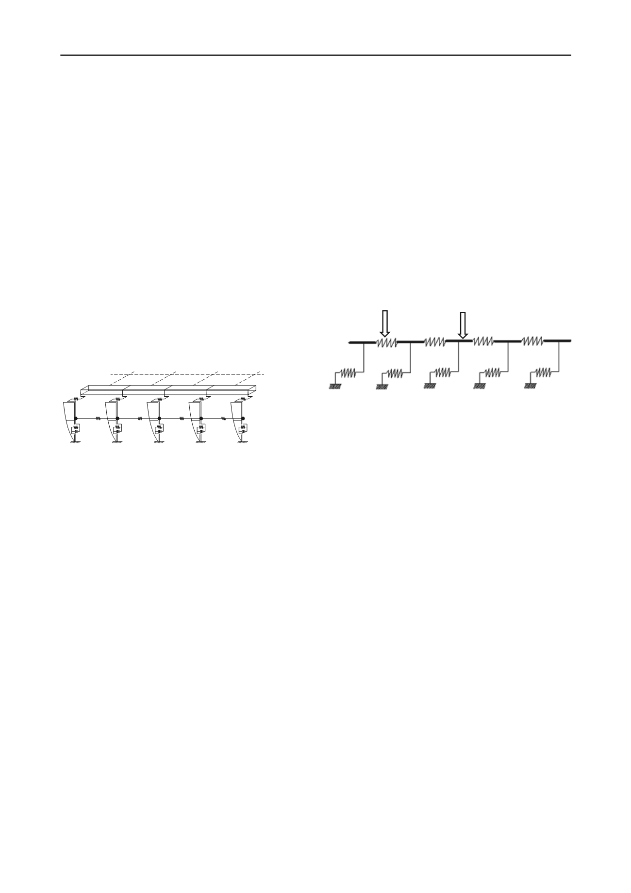
          2 RESPONSE DISPLACEMENT METHOD BY JSCE
        
        
          The response displacement method introduced here is based on
        
        
          a mass-spring model presented by the JSCE in 1988. It is
        
        
          assumed in this model that shear motion is the main vibration
        
        
          mode of strata on bedrock under seismic loading. In addition,
        
        
          there is another assumption that self-vibration characteristics of
        
        
          soil layers are not influenced by the existence of the tunnel. The
        
        
          soil around the immersed tunnel along the longitudinal direction
        
        
          is modeled as a series of particles. The springs and dashpots are
        
        
          used to connect adjacent particles, as well as particle and
        
        
          bedrock. The multi-segment tunnel is modeled as a beam with
        
        
          longitudinal translational springs located at segment joints. The
        
        
          segments and its surrounding soil particles are connected
        
        
          through calibrated interaction springs and dashpots (Fig. 2).


            k


            k


          -1


            k


          +1


            L


          k


            L


          k-1


            L


          k+1


            K


          1


            K


          2


            K


          3


            M


          e
        
        
          Figure 2. Mass-spring model under longitudinal seismic loading
        
        
          The response displacement method is a pseudo-static analysis
        
        
          approach and consists of two steps: (1) determining the free-
        
        
          field ground seismic deformation without considering the
        
        
          presence of tunnel; (2) imposing the ground deformation
        
        
          obtained in step one on the tunnel structure as a static load. The
        
        
          computational process in detail is described as follows.
        
        
          3 SEISMIC DEFORMATION OF FREE FIELD
        
        
          Seismic deformation of free field can be derived by solving
        
        
          dynamic equilibrium equation of the mass-spring model.
        
        
          According to D'Alembert principle, the dynamic equilibrium
        
        
          equation can be expressed as


            g s


            s


            s


            s s


            uM uK uC uM


          (1)
        
        
          where


            M


            s


          ,


            C


          and


            K


          = lumped mass coefficient, damping
        
        
          coefficient and stiffness coefficient, respectively;


            u


            s


          = response
        
        
          displacement of soil particles; and


            u


            g


          = seismic acceleration at
        
        
          the base of bedrock. The elements of tridiagonal symmetric
        
        
          stiffness matrix are expressed as


          1 1
        
        
          2
        
        
          3
        
        
          11


            k


            k k


          (2)


          ,
        
        
          3
        
        
          2
        
        
          2
        
        
          1 ( 2,3, , -1)


            i i


            k k i k i k i


            i


            n


          (3)


          1
        
        
          2
        
        
          3


            nk nk k


            nn


            ,


          (4)


            ) , ,,


            (


            -,


            n


            i


            i k


            k


            ii


          32 1
        
        
          2
        
        
          1


          (5)
        
        
          where


            k


            3


          = spring between soil particle and bedrock;


            k


            2


          = spring
        
        
          between adjacent soil particles;


            i


          = the number of the soil
        
        
          particle; and


            n


          = number of soil particles.
        
        
          Seismic displacement of the free-field soil at the base of the
        
        
          immersed tunnel can be obtained by


            s


            b


            u


            u


          (6)
        
        
          where


            u


            b


          = displacement of tunnels; and
        
        
          α
        
        
          = ratio of soil
        
        
          displacement at the base of the tunnel to that of soil particles.
        
        
          The calculation method for
        
        
          α
        
        
          is not given in this paper due to
        
        
          limitation of the space and the specific computational process
        
        
          have been presented in detail in the related reference (Zhou,
        
        
          1989).
        
        
          4 INTERNAL FORCE OF THE TUNNEL STRUCTURE
        
        
          The tunnel structure is modeled as a Winkler elastic foundation
        
        
          beam with joints, which is simplified into translational springs
        
        
          to simulate the behavior of compressing and tension of GINA
        
        
          gaskets under seismic loading (Fig. 3). The seismic response of
        
        
          the tunnel is obtained by applying the seismic displacement of
        
        
          free field to interaction springs between the tunnel and strata
        
        
          without considering the inertia of the tunnel. The seismic
        
        
          displacement of the tunnel can be obtained by


            t


            b


            t


            t


            u uK uK


          1
        
        
          (7)
        
        
          where


            K


            t


          and


            K


          1
        
        
          = stiffness matrix of the tunnel and interaction
        
        
          spring, in which


            K


          1
        
        
          is frequency-independent static stiffness;


            u


            t


          = seismic response displacement of the tunnel.
        
        
          Immersion joint
        
        
          Segment
        
        
          Figure 3. Simplified model of the immersed tunnel structure for response
        
        
          displacement method
        
        
          5 MODIFIED RESPONSE DISPLACEMENT METHOD
        
        
          Based on the Fast Fourier Transformation (FFT) technique and
        
        
          the theory of dynamic elastic Winkler foundation beam, a
        
        
          modified response displacement method is presented in this
        
        
          paper. Inertia of the immersed tunnel can be considered in this
        
        
          method as well as the dependency of soil-tunnel interaction
        
        
          parameters on the frequency of external seismic loading.
        
        
          5.1


            Seismic deformation of free field


          According to FFT, Eq. (1) given in Session 2.1 is changed into


            s


            s


            s


            s


            UK i


            UM


          ) 21(
        
        
          2
        
        
          (8
        
        
          )


            g s


            UM


          2


          where


            U


            s


          (
        
        
          ω
        
        
          ) and


            U


            g


          (
        
        
          ω
        
        
          ) = Fourier amplitude of particle and
        
        
          input seismic displacements, respectively;


            i


          = the imaginary unit;
        
        
          ξ
        
        
          = frequency-independent hysteretic damping ratio of the soil;
        
        
          and
        
        
          ω
        
        
          = external frequency of seismic loading. The response
        
        
          displacement of soil particle


            u


            s


          in the time domain can be
        
        
          obtained by the inverse Fast Fourier Transformation (IFFT) of


            U


            s


          (
        
        
          ω
        
        
          ).
        
        
          Likewise, eq. (6) can be changed into


            s


            b


            U


            U


          (9)
        
        
          where


            U


            b


          (
        
        
          ω
        
        
          ) = Fourier amplitude of the displacement of the soil
        
        
          at the base of the tunnel. Accordingly, the seismic displacement
        
        
          of the free-field soil at the base of the tunnel


            u


            b


          in the time
        
        
          domain can be obtained by IFFT of


            U


            b


          (
        
        
          ω
        
        
          ).
        
        
          5.2


            Internal force of the tunnel structure


          Inertia of the tunnel and dependence of soil-tunnel interaction
        
        
          parameters on external frequencies are taken into account in the
        
        
          modified response displacement method. The tunnel structure is
        
        
          discretized into a series of particles, which is combined with the
        
        
          soil through interaction springs and dashpots (Fig. 4). In
        
        
          addition, the form of external loading is the seismic acceleration