1708
Proceedings of the 18
th
International Conference on Soil Mechanics and Geotechnical Engineering, Paris 2013
Proceedings of the 18
th
International Conference on Soil Mechanics and Geotechnical Engineering, Paris 2013
carbonate components was found in medium-grained oolitic
limestone with maximum values of 8%, which is mostly given
by quartz and subordinately by feldspar.
3 METHODS
3.1
Sampling, core drilling and laboratory analyses
Samples were obtained from underground structures and surface
quarries. Additionally where it was avilable core drillings were
made.
For the laboratory analyses samples were drilled and cut
from porous limestone blocks or core drillings were processed.
Cylindrical test specimens were used and the following rock
mechanical tests were made according to European Norms: bulk
and material density (EN 1936), ultrasonic pulse velocity (EN
14579), water absorption (EN 13755) uniaxial compressive
strength (EN 1926), indirect tensile strength.
3.2
Numerical modelling
Different FEM codes were use to modell the cellars cut into
porous limestone such as Plaxis v8, Geo4 Tunnel module,
Phase2, Examine3D.
The first three codes use the same calculation methods but
they are able to use different material models. The Plaxis v8 and
the Geo4 are developed for modeling soils while the Phase
2
is
for modeling rocky environment. In spite of it the Plaxis and
Geo4 can be also used for rocks but the Phase
2
has some
specific material model for rock masses for example the Hoek-
Brown model, and it is able to calculate with the anisotropy of
the rock masses.
The porous limestone can be described as soft rock or hard
soil, therefore all of these codes can be used for modeling its
behaviour. The rock mass of the porous limestone is usually can
be considered as intact rock or blocky according to the chart of
Marinos & Hoek (2000). The joint system of the limestone is
characterized by faults or bedding. The Phase
2
has a good tool
for modeling the joints.
The geometry of the cellars sometimes very different, in the
area of Budapest can be found individual cellars, but sometimes
huge cellar systems as well. The cross-sectional area of them is
varies from 2 m
2
to more than 100 m
2
and there are cellar
systems which is above each other. The modeling of a cellar
system with such complicated geometry is not easy, sometimes
it is necessary to use 3D tools for example Examine3D. This
software is easy to use, but it is not able to consider different
layers and joints.
4 RESULTS
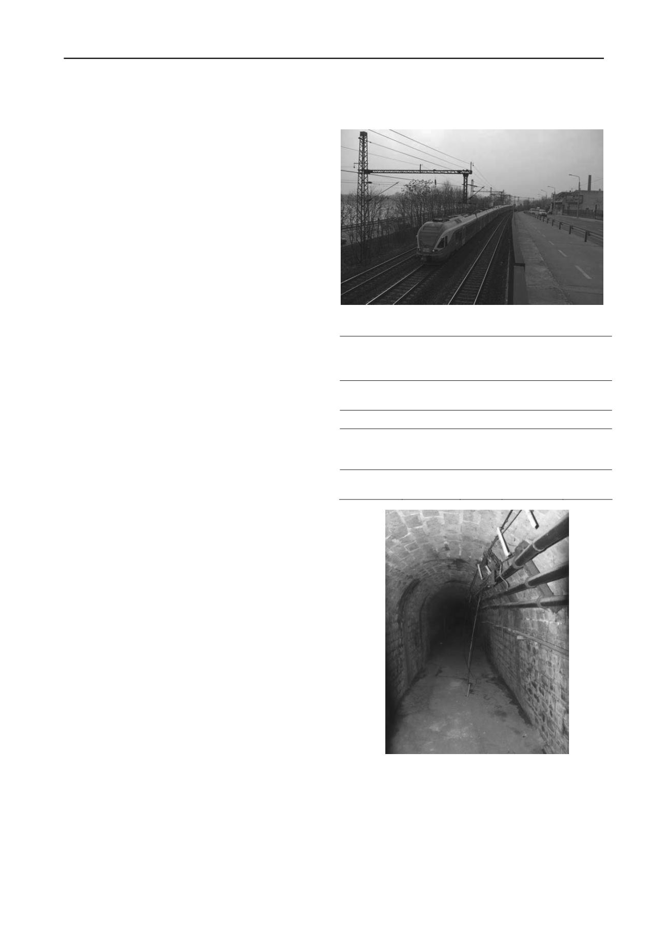
The paper provides three different cases on cellar system cut
into porous limestone. The first one is a more than a hunderd
years old individual cellar that was cut under a road and a
railway (Fig.1). There is a plan to enlarge the cross-section to
use the system as an access footpath to a huge cellar system.
The small cover above the tunnel is the major risk.
The second case is the study of the interaction of two cellar
systems, which are above each other.
The third case study deals with a cellar that is located just 3
metres below the surface. According to plans a new house is to
be built above.
4.1
Tunnel enlargement
The area of the first and the second case study is located very
close to each other, namely the planed tunnel goes into the
cellar system of the second case. Thus the differences between
them are the vertical placements of the cellars. The base level of
the tunnel is at 102.8 m Asl., while the base level of the second
one is about 106.5 m Asl. The geological set-up of the area of
the tunnel is showed in the table 1.
Figure 1. The road and the railway above the tunnel
Table 1. Layers and its parameters used for modeling
Layer
bulk density
(kg/m
3
)
friction
angle
(degree)
cohesion
(kPa)
rock mass
modulus
(MPa)
sandy clay
fill
1800
25
0
5
clayey rubble
1950
18
40
8
porous
limestone
rubble
1650
47
17
80
porous
limestone
1650
49
174
248
Figure 2. The tunnel with the concrete masonry support system
The cover of the tunnel is 1.3 m, and it has a concrete
masonry linning system (Fig.2).
Above the tunnel the clayey rubble layer is found, and
behind the tunnel lining the porous limestone rubble, while the
intact porous limestone only occurs under the base level of the
tunnel. The enlargement of it can be built by reducing the base
level of the tunnel. According to the drilling results behind the
concrete block masonry the void between the porous limestone
blocks are very high. Therefore the rock mass behind the


