1698
Proceedings of the 18
th
International Conference on Soil Mechanics and Geotechnical Engineering, Paris 2013
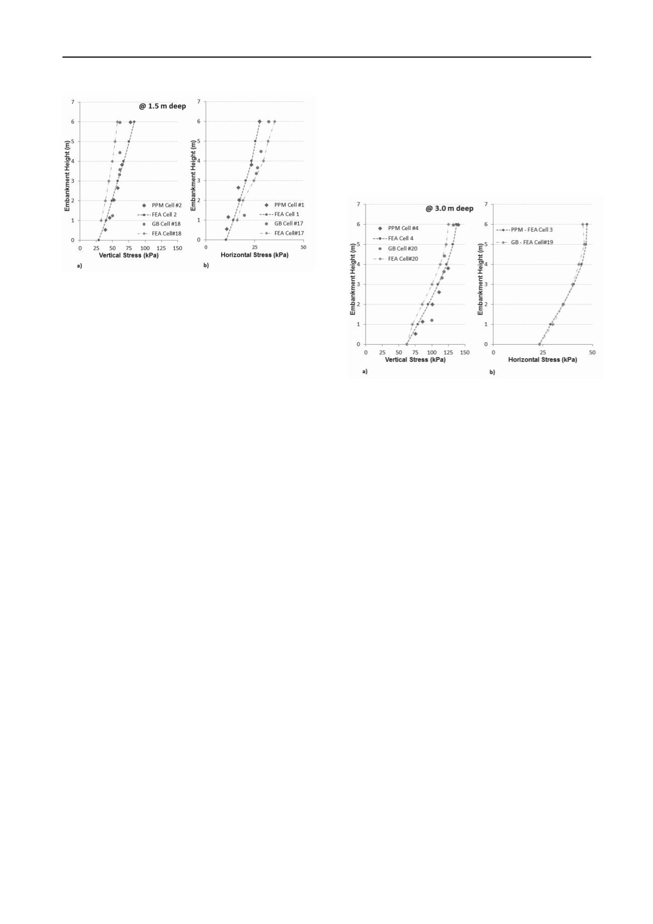
Figure 4. Compression of the FEA results with the vertical and
horizontal stresses data obtained from the field test at 1.5 m depth.
4.2
Stresses Measured at the Bottom of the Trench (3 m)
Figure 5 shows the variation of the vertical stresses that were
measured at 3.0 m depth in the trench (cells 4 for the PPM and
20 for the GB) and its comparison to the stresses predicted by
the FE analyses. Pressure Cells #3 and 19 that measures the
horizontal stresses were damaged during construction, thus
Figure 5b shows only the results of the FEA for these cells. The
stresses at this depth are also complex since their magnitude is
influenced not only by the installation method (i.e. the existence
of the 3 m wide crib in GB) but also the stress arching caused
by the lightly compacted surrounding above this location. The
measured and calculated stresses show a reasonable agreement
at this depth as well.
The results shown in Figure 5a indicate that the measured
vertical stresses increased as the embankment height was
increased. This increase ranges from 78 kPa to 140 kPa for PPM
installation and from 70 kPa to 125 kPa for the GB installation
for embankment heights of 1m and 6 m, respectively. The
results indicate that 11% reduction in vertical stresses is
achieved by the use of GB installation when the full
embankment height was achieved.
The results shown in Figure 5b indicate that the increased
embankment height increased the horizontal stresses from 23
kPa to 47 kPa for PPM installation. It should also be noted that
the difference between the horizontal stresses occurred at PPM
and GB cases was not as pronounced at this depth, possibly due
to the higher stiffness of well compacted granular surround and
as the depth increase the arching effect due to the 3 m wide
geogrid bridging softens.
5 SUMMARY AND CONCLUSION
A full scale instrumented test embankment was constructed by
Ontario Ministry of Transportation to study the effects of
embankment construction on the existing underground utilities.
The test embankment comprised four sections which facilitated
the evaluation of four configurations including the conventional
backfill, induced trenching and two at-grade geogrid reinforcing
bridging with different spans. Each configuration consisted of a
3 m deep trench underneath a 10 m wide, 10 m long and 6 m
high embankment section. The earth pressure cells were
installed to monitor stresses at the fill/ground interface and at
the depths of 1.5 m and 3 m. A numerical model of the full scale
instrumented test embankment was developed using the finite
element program PLAXIS. Both measured and estimated
material properties were utilized in the numerical analyses to
reproduce the trends of changes in stresses as a result of
installation methods. This paper presents the results of stress
measurements in a utility trench overlain by an embankment.
The measurements that were obtained both during and after
construction of a full-scale test embankment and results of
numerical modeling that helped clarify mechanisms of stress
reduction were presented. The performed analyses showed that
geogrid bridging has potential to reduce the stresses on buried
infrastructures at shallow depths; however, the magnitude of
reduction reduces with depth as the arching effect decreases.
Figure 5. Compression of the FEA results with the vertical and
horizontal stresses data obtained from the field test at 3.0 m depth.
6 ACKNOWLEDGEMENTS
The authors acknowledge and the financial support provided by
the New Brunswick Innovation Foundation (NBIF), and the
support provided by the Ontario Ministry of Transportation,
Material Engineering and Research Office.
7 REFERENCES
AASHTO "AASHTO LRFD Bridge Design Specifications", American
Association of State Highway and Transportation Officials,
Washington, 2007.
CHBDC,"Canadian Highway Bridge Design Code", Canadian
Standards Association, Rexdale, Ontario, 2006.
Haas, R.,Walls, J. and Carroll, R.G., 1988, “Geogrid Reinforcement of
Granular Bases in Flexible Pavements”, Transportation Research
Record 1188, pp. 19-27.
Love, J.P., 1984. Model testing of geogrids in unpaved roads.
Dissertation (Doctoral). University of Oxford, Oxford, UK.
OPSS 314 (1993), “Construction Specification for Untreated
Granular, Subbase, Base, Surface Shoulder and Stockpiling”,
Ontario Provincial Standard Specification.
PLAXIS BV (2011). Reference Manual PLAXIS BV: Amsterdam, the
Netherlands.


