 
          1689
        
        
          Technical Committee 204 /


            Comité technique 204


            Proceedings of the 18


            th


            International Conference on Soil Mechanics and Geotechnical Engineering, Paris 2013


          when the tunnel clearance is smaller than 0.8. In addition, the
        
        
          results indicate a significant difference (about 20%) of stress on
        
        
          both sides of the tunnel when the tunnel clearance is about 0.2.
        
        
          Table 1. Suggestion of additional surcharge with respect to tunnel
        
        
          clearance (after JRCEA 1977)
        
        
          Tunnel clearance, a
        
        
          Additional surcharge /


          v
        
        
          ’
        
        
          1.0 < a
        
        
          0
        
        
          0.9 < a
        
        
          ≦
        
        
          1.0
        
        
          0.1
        
        
          0.8 < a
        
        
          ≦
        
        
          0.9
        
        
          0.2
        
        
          0.7 < a
        
        
          ≦
        
        
          0.8
        
        
          0.3
        
        
          0.6 < a
        
        
          ≦
        
        
          0.7
        
        
          0.4
        
        
          0.5 < a
        
        
          ≦
        
        
          0.6
        
        
          0.5


          v
        
        
          ’
        
        
          : vertical effective earth pressure acting on segments
        
        
          Figure 6. Variation of induced vertical stress on top of preceding tunnel
        
        
          with tunnel clearance (after Kang et al. 2007)
        
        
          Figure 7. Variation of induced lateral stress on two sides of preceding
        
        
          tunnel with tunnel clearance (after Kang et al. 2007)
        
        
          Following the interaction analysis results for twin tunnels,
        
        
          the commercial software SAP2000 (CSI 2008) was exploited to
        
        
          derive the resulting bending moment and stress around the
        
        
          lining of the preceding tunnel. Table 2 shows the results for the
        
        
          tunnel clearance of about 0.3. The bending moment and axial
        
        
          force is increased by about 70% and 30%, respectively, as
        
        
          compared to those for single tunnel cases (i.e. without close
        
        
          proximity effect). As the tabulated results are plotted onto the
        
        
          force-moment diagram, Figure 8 implies that the results
        
        
          exceeded the ultimate capacity of precast RC segments with
        
        
          reinforcement ratio equal to 3%. Several reinforcement
        
        
          measures, such as ground improvement and increase of lining
        
        
          thickness, were then evaluated during design stage. Considering
        
        
          that most of sections that are influenced by proximity effect are
        
        
          beneath existing structures or roads of heavy traffic where
        
        
          ground improvement or the thickened RC segments may not be
        
        
          able to achieve the protection requirement effectively, the
        
        
          spherical graphite cast iron segments (or ductile segments) were
        
        
          employed for the first time in the
        
        
          Taiwan’s MRT system.
        
        
          Table 2. Resulting response of lining with and without proximity effect
        
        
          (after Kang et. al 2007)
        
        
          Design condition Axial force (kN) Bending moment (kN-m)
        
        
          Single tunnel
        
        
          2,630
        
        
          206
        
        
          Tunnels with tunnel
        
        
          clearance 0.3
        
        
          3,335
        
        
          352
        
        
          Figure 8. Analysis results on force-moment curve for RC segments of
        
        
          3% reinforcement ratio (after Kang et al. 2007)
        
        
          4 BASIC INFORMATION AND DESIGN
        
        
          CONSIDERATION OF DUCTILE SEGMENTS
        
        
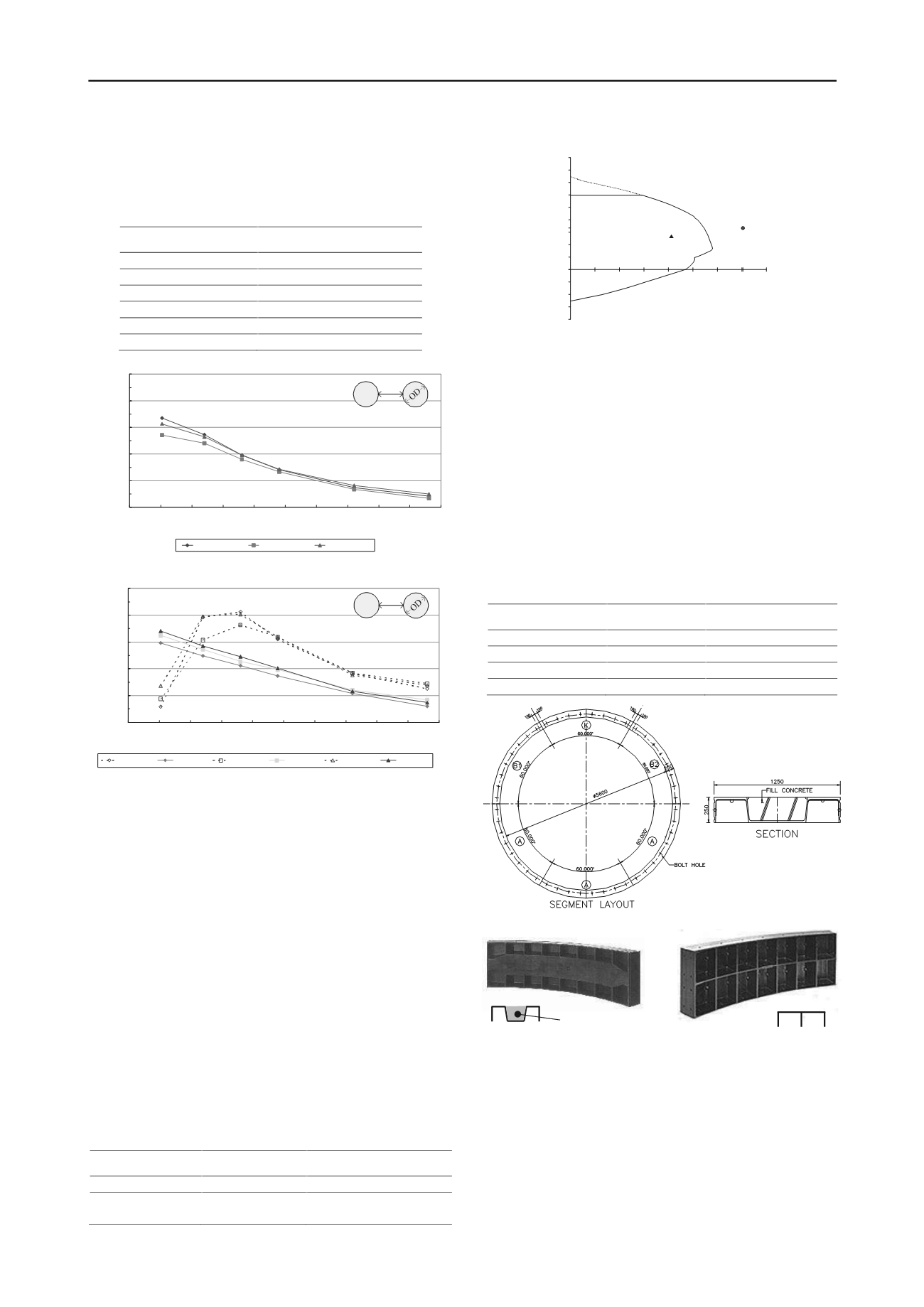
          The ductile segments were chosen because of the high degree of
        
        
          strength, ductility, and anticorrosion characteristics that provide
        
        
          sufficient capacity against additional surcharge and deformation
        
        
          induced by proximity effect. The basic information of RC
        
        
          segments used in TRTS and the proposed ductile segments is
        
        
          summarized in Table 3. Figure 9 depicts the layout of ductile
        
        
          segments. As shown in the figure, the proposed ductile
        
        
          segments were corrugated type that could exhibit higher
        
        
          bending capacity than the girder counterpart (Figure 10). With
        
        
          corrugated segments backfilled with concrete, the enhancement
        
        
          of lateral support can further lead to a more economic design.
        
        
          Table 3. Basic information of RC and ductile segment used in TRTS
        
        
          Item
        
        
          RC segment
        
        
          Ductile segment
        
        
          Thickness (m)
        
        
          0.25
        
        
          0.25
        
        
          Length (m)
        
        
          1.0
        
        
          1.25
        
        
          Segments in a ring 6 (unequal size)
        
        
          6 (equal size)
        
        
          Bolt
        
        
          curved
        
        
          high strength, straight
        
        
          Figure 9. Typical layout of ductile segments (after Kang et al. 2007)
        
        
          Figure 10. Structural type of ductile segments
        
        
          While the loading combination and analysis model are
        
        
          similar for precast RC and ductile segments, there are some
        
        
          points that shall be considered in the design of ductile segments.
        
        
          These include effective section, analysis model, plate and
        
        
          component design, and connection design that can be referred to
        
        
          Kang et al (2009) for details.
        
        
          By taking the consideration into account, the ductile
        
        
          segments were designed, fabricated, and then employed at the
        
        
          preceding tunnel, the up-track line tunnel in the case, for
        
        
          sections where the tunnel clearance is smaller than 0.5.
        
        
          100%
        
        
          120%
        
        
          140%
        
        
          160%
        
        
          180%
        
        
          200%
        
        
          0.0
        
        
          0.2
        
        
          0.4
        
        
          0.6
        
        
          0.8
        
        
          1.0
        
        
          1.2
        
        
          1.4
        
        
          1.6
        
        
          1.8
        
        
          2.0


            TunnelClearance(L/D)


            Pressure Ratio(Dual System/ Single System)


          Z=20m_crown
        
        
          Z=25m_crown
        
        
          Z=30m_crown
        
        
          D
        
        
          L
        
        
          Vertical Pressures
        
        
          100%
        
        
          110%
        
        
          120%
        
        
          130%
        
        
          140%
        
        
          150%
        
        
          0.0
        
        
          0.2
        
        
          0.4
        
        
          0.6
        
        
          0.8
        
        
          1.0
        
        
          1.2
        
        
          1.4
        
        
          1.6
        
        
          1.8
        
        
          2.0


            Tunnel Clearance(L/D)


            Pressure Ratio(DualSystem/ Single System)


          Z=20m_inner
        
        
          Z=20m_outer
        
        
          Z=25m_inner
        
        
          Z=25m_outer
        
        
          Z=30m_outer
        
        
          Z=30m_outer
        
        
          D
        
        
          L
        
        
          Lateral Pressures


            Vertical Stress


          StressRatioof Do ble to Single Tu nelSystem


            T learance (s/O )


          s
        
        
          1.6
        
        
          1.8
        
        
          2.0
        
        
          crown
        
        
          D
        
        
          L
        
        
          100%
        
        
          110%
        
        
          120%
        
        
          130%
        
        
          140%
        
        
          150%
        
        
          0.0
        
        
          0.2
        
        
          0.4
        
        
          0.6
        
        
          0.8
        
        
          1.0
        
        
          1.2
        
        
          1.4
        
        
          1.6
        
        
          1.8
        
        
          2.0


            Tunnel Clearance(L/D)


            Pressure Ratio(DualSystem/ Single System)


          Z=20m_inner
        
        
          Z=20m_outer
        
        
          Z=25m_inner
        
        
          Z=25m_outer
        
        
          Z=30m_outer
        
        
          Z=30m_outer
        
        
          D
        
        
          L
        
        
          Lateral Pressures


            Lateral Stress


          StressRatioof Double to Single TunnelSystem


            Tun l learance (s/OD)


          s
        
        
          9000
        
        
          -4000
        
        
          P(kN)
        
        
          352
        
        
          Mx (kN-M)
        
        
          300
        
        
          200
        
        
          100
        
        
          5000
        
        
          3335
        
        
          0
        
        
          (1)
        
        
          (2)
        
        
          (1) Single tunnel
        
        
          (2) Tunnels with tunnel clearance 0.3
        
        
          (a) Corrugated type
        
        
          (b) Girder type
        
        
          concrete