1696
Proceedings of the 18
th
International Conference on Soil Mechanics and Geotechnical Engineering, Paris 2013
and to gain an understanding of the stress reduction mechanism.
This paper presents the results of stress measurements inside the
trench protected using at-grade geogrid bridging as well as the
results of numerical model that helped clarify mechanisms of
stress reduction. The material presented in this paper is
considered to be of interest to researches and engineers.
2 METHODOLOGY
2.1
Description of the field test
An instrumented test embankment is constructed by Ontario
Ministry of Transportation over a 3 m deep trench to study the
effects of embankment construction on the underground
utilities. The test embankment is constructed as part of Highway
407 contract and is located near the Highway 407 and Weston
Road in Vaughan, Ontario. The test embankment comprised
several sections which facilitated the evaluation of four different
configurations including the positive projection installation,
induced trench installation and at-grade geogrid reinforcing
bridging. Since the objective of the testing program was to
evaluate the stresses reductions achieved by each of the
considered installation techniques, no actual culverts were
installed. Instead, the earth pressure cells were placed in
granular protective surrounds located at two different depths in
the trench. The first section is constructed as a conventional
control section (Section 1), which included an instrumented
trench that was conventionally backfilled with granular material
up to the grade level (Positive Projection Method). The second
section represents an Induced Trench Method installation (ITM)
(Section 2), which included an instrumented trench that was
backfilled with granular material that is overlain by a layer of
compressible Styrofoam chips up to the grade level. The third
and fourth sections include geogrid void bridges installed on the
instrumented trenches with different trench widths. The
evaluation of the induced trench method installation section was
performed as part of a separate study and is beyond the scope of
the present work. This study involve the results of the PPM
represented in Section 1 (the control case) and the 3 m wide at-
grade geogrid bridging, GB (Section 4). The following is a
general description of field tests. The layout of test embankment
is depicted in Figure 1. The considered test configuration
comprises a 3 m deep trench backfilled up to the grade level
which underlies an embankment with the footprint dimension of
64m x 34m in length and width and with a height of 6 m. The
slopes of the embankment were constructed with a 2H:1V
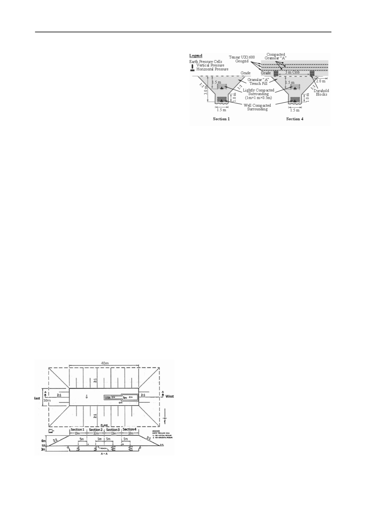
inclination. Figure 2a and 2b show the details of instrumented
trenches for Section 1 and 4, respectively.
Figure 1. Plan and Profile of Test Embankment
Figure 2. Details of the instrumented trenches
2.2
Construction and Instrumentation
The site was leveled and topsoil was removed prior to the
construction of the test embankment. A 1.5 m wide trench was
excavated to a depth of 3m. 1m above the bottom of trench,
trench slopes were cut to 1H:1V to maintain the integrity of
trench side slopes during the construction (see Figure 2). Two
drainage sumps are installed at each end to maintain a dry
condition in the trench. The base of the trench is filled with a
300mm thick compacted granular pad comprising Granular-A
(OPSS 314). Then, the installation of earth pressure cells was
initiated. Earth pressure cells with vibrating wire pressure
transducers were used. The earth pressure transducers were
placed at the bottom (3m from the grade) and the mid-height
(1.5 m from grade) of the trench with horizontal and vertical
orientations in order to allow measurement of vertical and
horizontal pressures, respectively. The pressure transducers
were placed in a 0.5m x 1m x 1m granular protective surrounds.
The granular surrounds were constructed as lightly compacted
at mid-height pressure cell and well compacted at the bottom
pressure cell to see the effect of the surround compaction on the
measured stresses. The protective surrounds, which were
constructed to eliminate a possible damage to pressure cells
were constructed using steel separators in four sides. The steel
separators separate the lightly compacted and well compacted
granular surrounds from compacted Granular-A, which
constitutes the rest of the fill material in the trench. The steel
separators were removed as the level of granular surrounds
reached 0.5 m height. A total of 2 transducer couples (vertical
and horizontal) were installed at the bottom and mid-height of
each trench for each section and an additional transducer is
installed at the interface between trench backfill and
embankment. The trench backfill encapsulating granular
surrounds, comprise Granular A compacted to 95% of Standard
Proctor Dry Density. The pneumatic lines were extended
through a PVC pipe, which followed the edges of trench and
connected to a monitoring station.
The embankment was constructed using native cohesive soils in
the area. The soil was placed in the lift of 300mm and
compacted to 95% of Standard Proctor Dry Density. The
portion of the embankment fill immediately above the trench
was placed by hand and compacted by self-propelled
compaction equipment (Bomag BW65S) in order to protect
against heavy machine loading used for compaction of
embankment fill. The embankment fill, including the zone
above the trench, is compacted using regular compaction
equipment after fill height reached 1.3 m.


