 
          1700
        
        
          Proceedings of the 18
        
        
          th
        
        
          International Conference on Soil Mechanics and Geotechnical Engineering, Paris 2013


            Proceedings of the 18


            th


            International Conference on Soil Mechanics and Geotechnical Engineering, Paris 2013


          Depth (m)
        
        
          Boring log
        
        
          SB-16
        
        
          Description
        
        
          10
        
        
          GWT
        
        
          Surface fill (CL)
        
        
          N = 3-7
        
        
          w = 17.9%
        
        
          w
        
        
          L
        
        
          = 21
        
        
          w
        
        
          P
        
        
          = 8
        
        
          Sublayer V
        
        
          Silty sand (SM)
        
        
          N = 14-22
        
        
          w = 20.2-27.3%
        
        
          Sublayer IV
        
        
          Silty clay (CL)
        
        
          N = 14-22
        
        
          w = 23.3-33.1%
        
        
          w
        
        
          L
        
        
          = 22-46
        
        
          w
        
        
          P
        
        
          = 2-20
        
        
          Sublayer III
        
        
          Silty sand (SM)
        
        
          N = 16-23
        
        
          w = 16.9-23.8%


            6m


            26m


            35m


          SF


            23m


          20
        
        
          30
        
        
          Jet
        
        
          grouting
        
        
          zone
        
        
          sump
        
        
          Drainage
        
        
          Cross
        
        
          passage
        
        
          6.1m
        
        
          Shield Tunnel
        
        
          13.5 m
        
        
          23.5 m
        
        
          8.2 m
        
        
          Down-Track
        
        
          tunnel
        
        
          Up-Track
        
        
          tunnel
        
        
          Cross passage
        
        
          Drainage
        
        
          sump
        
        
          JSG soil
        
        
          improvement
        
        
          Down-Track
        
        
          Tunnel
        
        
          Up-Track
        
        
          Tunnel
        
        
          Cross
        
        
          passage
        
        
          JSG


          = 1.4 m
        
        
          Drainage
        
        
          sump
        
        
          5.6 m
        
        
          6.1 m
        
        
          9.4 m
        
        
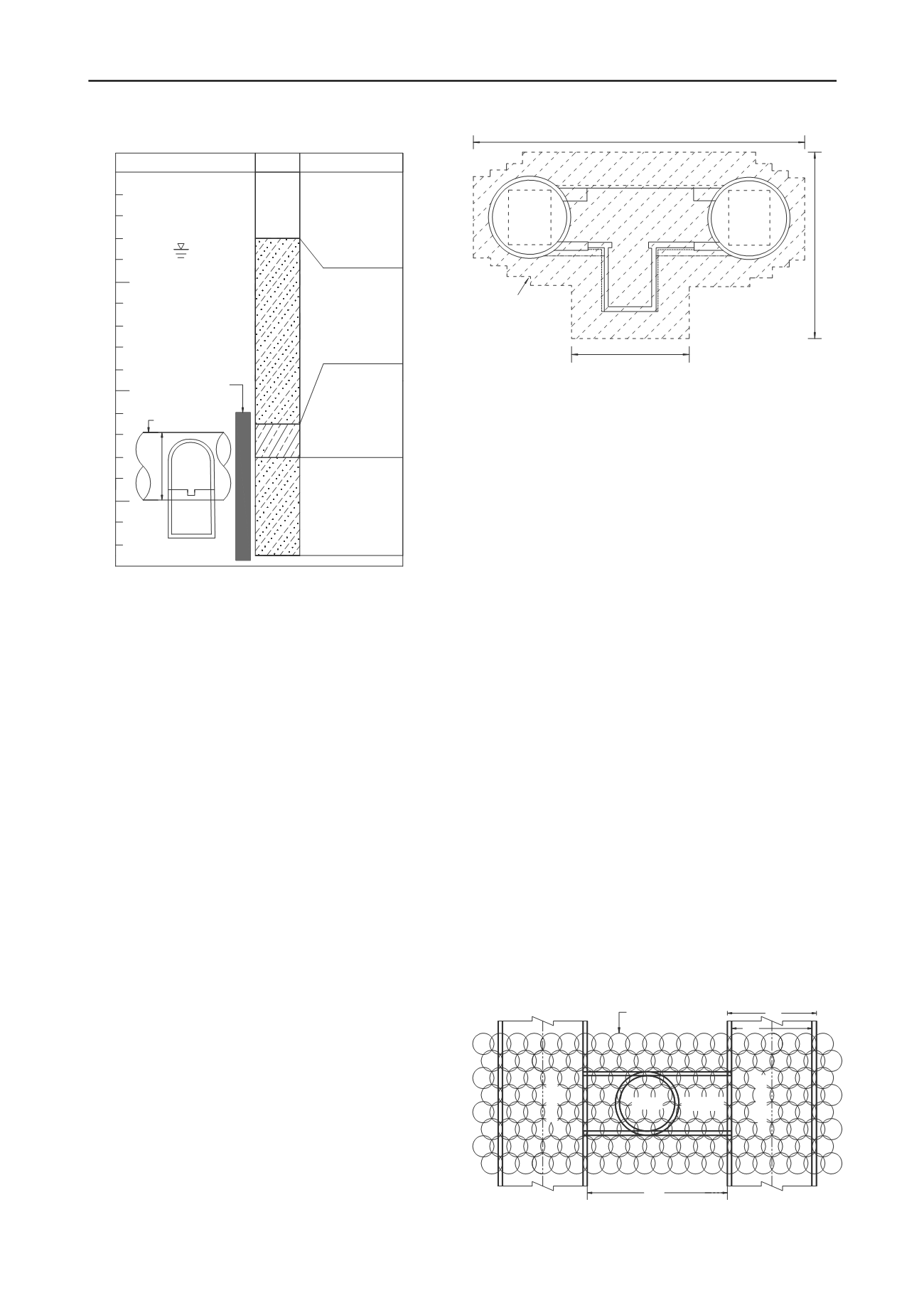
          Figure 2. Geological profile for excavation of cross passage and
        
        
          drainage sump. (after Continental Engineering Corp., 2003)
        
        
          1992), Figure 2 shows the geological profile adjacent to the
        
        
          cross passage. In the figure, the groundwater table was at about
        
        
          7 m below ground level.
        
        
          Figure 2 shows the cross passage was constructed at the depth
        
        
          of 24.7 to 29.3 m. Plus the 4.4 m-deep drainage sump, the
        
        
          excavation was extended to the depth of 33.7 m. Soils excavated
        
        
          for the cross passage included silty clay (classified as CL) and
        
        
          silty sand (classified as SM). Engineering properties of these
        
        
          soil deposits, such as the natural water content w, standard
        
        
          penetration test blow count N, liquid limit w
        
        
          L
        
        
          and plastic limit
        
        
          w
        
        
          P
        
        
          were indicated in Figure 2.
        
        
          JSG (Jumbo Special Grout) operation was completed before
        
        
          the shield machine arrived. Based on the size of the cross
        
        
          passage and the recommendations of the Jet Grout Technical
        
        
          Information (JJGA 1990), the grouting zone was 13.5 m-high,
        
        
          and 8.2 to 23.5 m-wide as illustrated in Figure 3. Figure 4
        
        
          shows a total of 168 1.4 m-diameter JSG piles were fabricated.
        
        
          2.2


            JSG operation and quality control


          The technique of JSG utilizes high-pressure water-cement jet
        
        
          streams (sheathed with air pressure) to cut, replace and mix with
        
        
          native soils. For every 1 m
        
        
          3
        
        
          of jet grout, 600 kg of type I
        
        
          Portland cement was mixed with 0.81 m
        
        
          3
        
        
          of water. The jetting
        
        
          pressure was controlled at 19.6 MPa (200 kgf/cm
        
        
          2
        
        
          ), and the rate
        
        
          of flow was 0.06 m
        
        
          3
        
        
          /min. The air pressure used was 0.6 to 0.7
        
        
          MPa (6 to 7 kgf/cm
        
        
          2
        
        
          ). The grouting rod was controlled to rotate
        
        
          at 6 to 7 r.p.m., and to uplift at the speed of 2.0 m/hr.
        
        
          After ground improvement, soilcrete cores were drilled and
        
        
          field permeability tests were carried out. The minimum core
        
        
          recovery of 80% and the maximum coefficient of permeability
        
        
          of 1 x 10
        
        
          -7
        
        
          m/s were required for the improved body. 28 days
        
        
          after grouting, the design specification requires the uniaxial
        
        
          compressive strength of sample obtained from sandy and clayey
        
        
          layer should reach at least 2.94 MPa (30 kgf/cm
        
        
          2
        
        
          ) and 0.98 MPa
        
        
          (10 kgf/cm
        
        
          2
        
        
          ), respectively. For more information regarding the
        
        
          JSG application for the construction of Taipei MRT, the reader
        
        
          is referred to Fang and Chung (1997), Fang and Yu (1998), and
        
        
          Figure 3. Section of JSG ground improvement for cross passage.
        
        
          Fang et al. (1993, 1994a, 1994b).
        
        
          3 CONSTRUCTION OF CROSS PASSAGE
        
        
          3.1


            Preparation


          Due to the pushing, cutting and disturbing of the cutter disc of
        
        
          the EPB shield tunneling machine, cracks and discontinuities in
        
        
          the improved ground might be induced. As a result, the
        
        
          water-leak test on the jet-grouted body became necessary.
        
        
          Figure 5 shows holes were drilled from the tunnel to the
        
        
          soilcrete to investigate the quality of ground modification. The
        
        
          holes should not penetrate the improved ground as to create new
        
        
          intruding paths for groundwater. When a significant amount of
        
        
          water-leak was measured in the tunnel (see Figure 6), additional
        
        
          chemical grouting was conducted as indicated in Figure 7. Low
        
        
          pressure grout with a mixture of water-glass and SL reaction
        
        
          agent was injected to the improved ground to seal all water
        
        
          paths around the cross passage.
        
        
          To repress the inflow of groundwater at the face of
        
        
          excavation, and to increase the safety of construction, the
        
        
          compressed-air method was employed. The air-lock used is
        
        
          shown in Figure 8. For most of the working days, the air
        
        
          pressure was kept at 60 to 80 kPa, and the maximum air
        
        
          pressure used was about 180 kPa.
        
        
          For the mining of the cross passage, circular holes were cut
        
        
          on the steel segments of the main MRT tunnels. The load
        
        
          release on the opening would cause a redistribution of pressure
        
        
          on the tunnel lining, and a possible stress concentration on
        
        
          adjacent lining segments. For this reason, Figure 9 shows the
        
        
          contractor fabricated octagonal steel reinforcements on both
        
        
          sides of the opening in the tunnel for protection.
        
        
          3.2


            Excavation


          The excavation of cross passage was conducted manually. The
        
        
          digging was divided into four parts: (1) top heading (the upper
        
        
          part); (2) bench (the middle part); (3) invert (the lower part);
        
        
          Figure 4. Plan of JSG ground improvement for cross passage.