1720
Proceedings of the 18
th
International Conference on Soil Mechanics and Geotechnical Engineering, Paris 2013
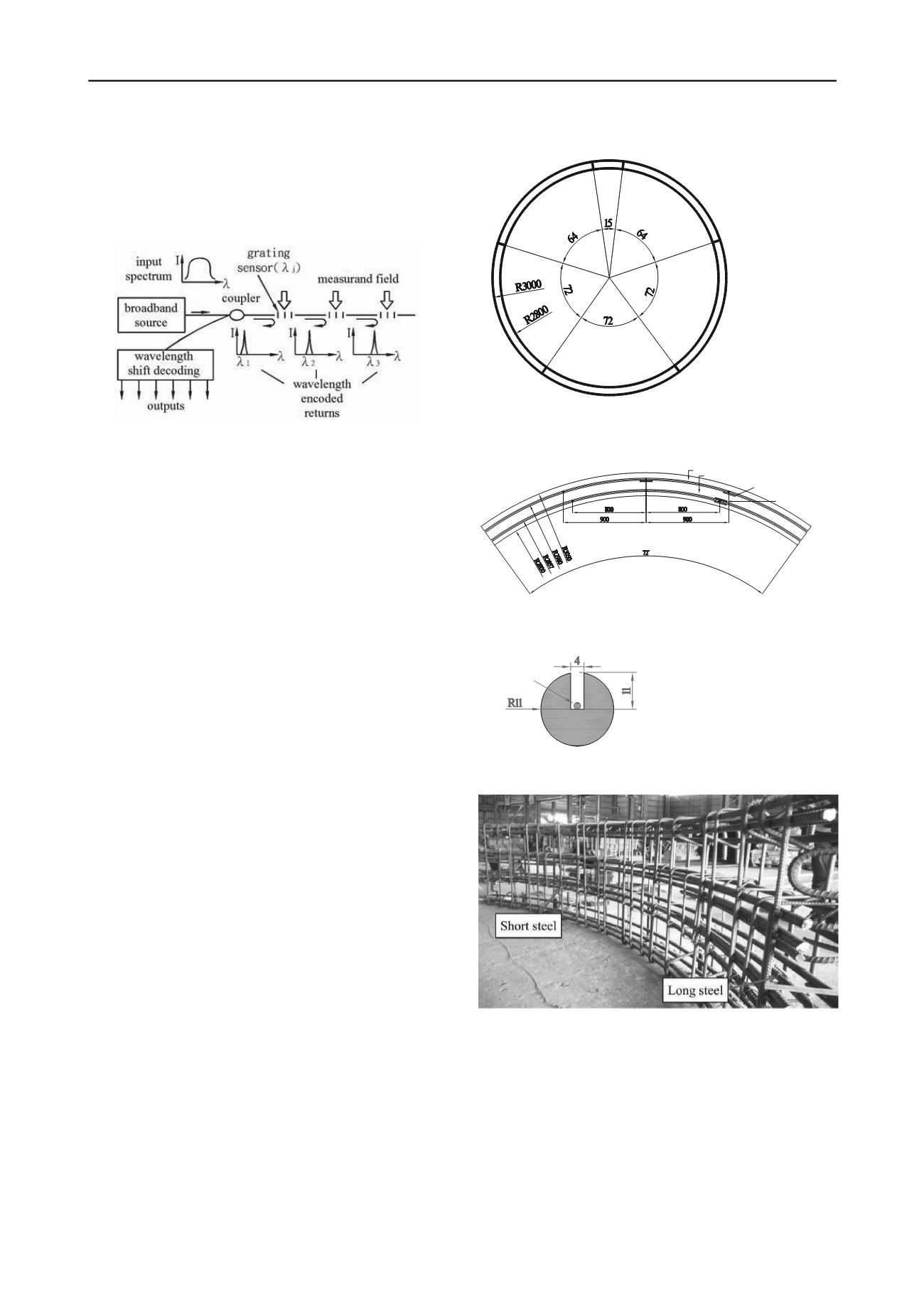
multiplexing among various sensors on a single fibre can be
accomplished by wavelength division addressing as
conceptually described in Figure 1. The FBG is partially
distributive because only those parts of the optical fibre with
FBG are used as strain sensors and these sensors can share the
same optical fibre transmission line.
Figure 1. Schematic diagram of Fibre Bragg Grating
(Kersey 1992), I = light intensity
wavelength.
The authors developed the techniques to install FBG strain
sensors on the tunnel lining panel reinforcement prior to
concrete casting. FBG strain readings could be recorded during
panel concrete curing, shipping, before and after field
installation for long term monitoring. The absolute strains
experienced by the lining panel could be determined according
to baseline readings taken before installation and data recorded
following the completion of the tunnel lining. The authors
developed the techniques of attaching FBG strain sensors and
other FBG based sensors to the reinforcement and/or the tunnel
lining panel. The techniques were first applied at Taipei MRT
Xinyi line, installation of the first FBG sensored shield tunnel
panel was completed on March 24, 2008. Continuous,
automated strain readings were recorded from January 1, 2010
to April 26, 2012. The paper describes the techniques of FBG
sensor installation, the case of applying this technique to Taipei
MRT Xinyi line, presents available records and discusses
implications in the design and safety monitoring of shield tunnel
linings.
2 FBG STRAIN SENSOR INSTALLATION AND PANEL
LOAD TEST
Figure 2 shows a typical cross section of the Taipei MRT Xinyi line
tunnel. It has an outside diameter of 6m and a thickness of 200mm. The
tunnel lining is fabricated by assembling six, 1m long pre-cast concrete
panels. The designations and the dimensions of these panels are shown
in Figure 2. For the case reported herein, FBG strain sensors were
installed in panels A1, A3 and B. For each panel, an inner (short) and an
outer (long), No. 7 reinforcement steel was selected for instrumentation.
Three FBG strain sensors were attached to the designated reinforcement
steel. The FBG’s on the long steel were numbered in the clockwise
direction while those on the short steel were numbered in the counter
clockwise direction. Figure 3 shows the locations and numbering the
FBG strain sensors for the case of A1 panel. An electrical thermo
couple and a vibrating wire (VW) strain gage were also installed as
shown in Figure 3 to provide reference values. A 4mm wide and 11mm
deep channel was milled into the reinforcement steel as schematically
shown in Figure 4. The optical fibre along with the FBG’s were
attached to the bottom of the channel. For strain measurement, the
FBG’s were epoxied to the surface of a well-polished and cleaned steel
surface. A separate FBG, designated as FBG (T) sealed inside a tubing,
so that it is not making contact with the steel, was placed next to
FBG2(L) and served as a temperature sensor. The empty space of the
channel was then filled with epoxy. This arrangement minimizes the
effects of local bending of steel on FBG strain readings and provides
good protection of the optical fibre during casting and handling of the
panel. Figure 5 shows a fully assembled reinforcement steel cage with
all FBG sensors included.
A1
A2
A3
C
K
B
Forward Direction
Unit : mm
¢X
¢X
¢X
¢X
¢X
¢X
Figure 2. Cross section of the Taipei MRT Xinyi line tunnel.
VW strain gauge
Long steel
short steel
FBG3(L)
FBG2(L)
FBG1(L)
FBG3(S)
FBG2(S)
FBG1(S)
Unit
:
mm
Thermo couple
Figure 3. Numbering of FBG strain sensors in A1 panel.
Optical fiber
Unit:mm
Figure 4. Placement of optical fiber in reinforcement steel.
Figure 5. A fully assembled reinforcement steel cage for A1 panel.
The precast concrete panels were manufactured in a factory. The
reinforcement steel cage along with low slump concrete were placed in
a steel mold and subjected to vibration. Upon initial setting and de-
molding, the panel was cured in a steam room and followed by
submerging under water for three days before taking out and undergo
the rest of the curing in the air. The effects of this harsh environment are
reflected in the sharp increase in the FBG wave length during steam
curing as shown in Figure 6. Every one pm (10
-12
m) wavelength change
corresponds to approximately 1
of strain. The continued readings
assure the integrity and functionality of the FBG’s during the curing
stage of the panel.


