1746
Proceedings of the 18
th
International Conference on Soil Mechanics and Geotechnical Engineering, Paris 2013
4 COMPARISON OF DEFORMATION BEHAVIOUR
BETWEEN GROUTED AND NON TREATED AREAS
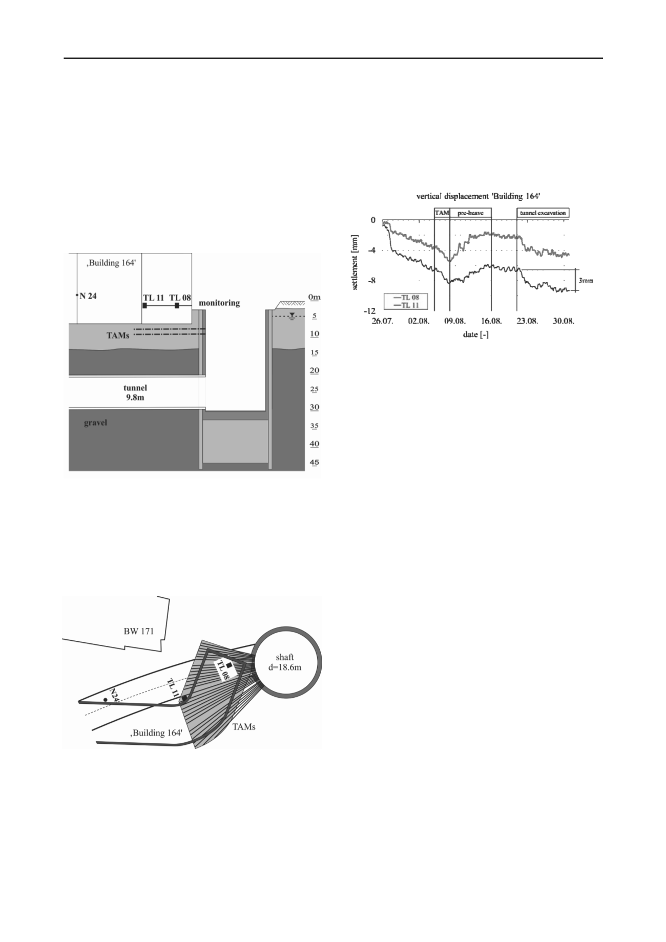
The efficiency of compensation grouting was proven during the
TBM excavation underneath ‘Building 164’ (see Fig. 11). This
5 storey building with shallow foundations is located next to the
exit shaft which is filled with water sealing material to allow for
the entrance of the TBM. The soil profile is determined by fill
and sandy soil, underlain by gravel in the tunnelling section.
The groundwater table is 4 m below ground surface. The cover
between the footings and the 9.8 m diameter tunnel is ca. 13 m.
The TAM array with two layers of grouting pipes was designed
in function of the risk assessment.
Figure 11. Cross section of ‘Building 164’.
The plan view of ‘Building 164’ with respect to the tunnel
excavation and the exit shaft is depicted in Fig. 12. The TAM
array covers the building only in the part of the building where a
major risk of settlement was assumed when entering in the final
shaft (while cutting the diaphragm wall). A large number of
water gauges and precise levelling points were installed on the
structure to assess the deformation.
Figure 12. Plan view of the ‘Building 164’ next to the exit shaft.
The implementation of the grouting pipes took place after
settlements were observed during the approach of the TBM.
Fig. 13 shows the vertical displacement of 2 monitoring points
of ‘Building 164’ during the excavation of the TBM. These
instruments are the liquid levels TL 08 and TL 11 installed in
the compensated area. To compare with the settlement in the
untreated zone, precise levelling point N 24 is also indicated in
Fig. 12. In monitoring point N 24 the maximum final settlement
for this building was measured with 20 mm after the TBM has
passed. Both liquid levelling points clearly show the effect of
grouting with a maximum settlement of 10 mm (TL 11). The
settlement during the tunnel excavation was significantly lower
(approx. 3 mm for TL 11). It has to be mentioned that
settlement compensation in the transition zone between the
untreated and the grouted area had to be limited in order to
avoid undue differential settlements.
Figure 13.Vertical displacements due to tunnelling and grouting activity
in distinct monitoring points.
5 CONCLUSIONS
Compensation grouting was used for the construction of Metro
B1 in Rome to limit absolute and differential settlements in
critical areas, where the risk of damaging the buildings has high.
The buildings were founded on shallow foundations and piles.
Due to compensation grouting operations, settlements were
significantly below the tolerable values and confirm the
efficiency of the building protection measure technically and
economically both for shallow and deep foundations.
For the design of these compensation grouting projects it
was fundamentally to establish the grouting strategy by means
of full-scale field trials.
6 REFERENCES
Falk E. and Kummerer C. 2012.
Ground improvement – Chapter 7:
Soilfracture Grouting
. Ground Improvement 3
rd
edition, eds.
K.Kirsch and A.Bell, CRC Spoon, Francis&Taylor.
Kummerer C., Falk E. and Gularte, F. 2012.
State of the Art of
Compensation Grouting with HDD drillings and deep foundations
.
Proceedings of the 4
th
International Conference on Grouting and
Deep Mixing, New Orleans, 914-924.
Sciotti A., Desideri A., Saggio G. and Kummerer, C. 2011
. Mitigation
of the effects induced by shallow tunneling in urban environment.
The use of 'compensation grouting' in the Underground Line B1
works in Rome
. Proceedings of the 7
th
International Symposium on
"Geotechnical Aspects of Underground Construction in Soft
Ground”, Rome, CRC Press, Taylor&Francis.


