786
Proceedings of the 18
th
International Conference on Soil Mechanics and Geotechnical Engineering, Paris 2013
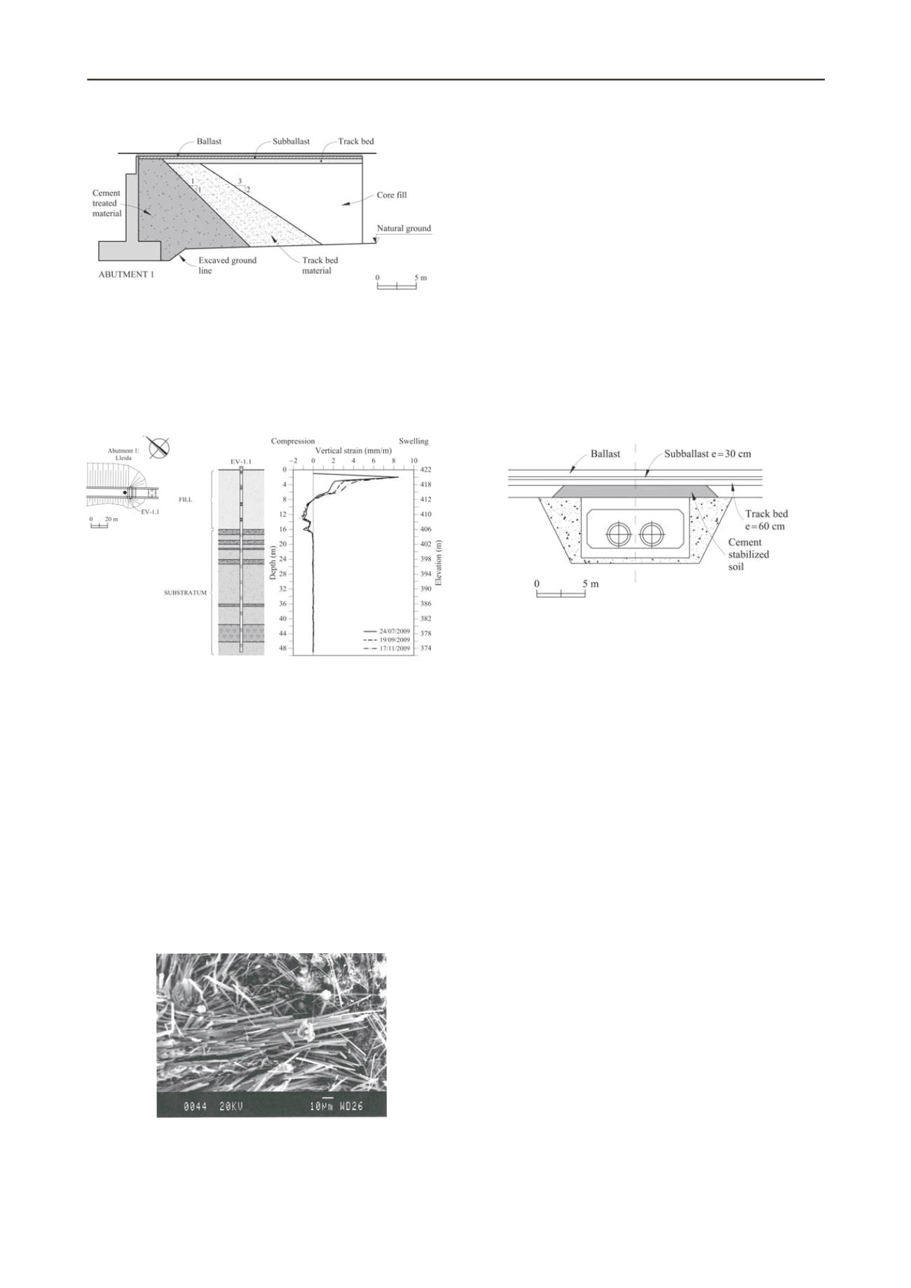
Figure 1. Design of the embankment
Inclinometers installed in boreholes indicated that swelling
deformations occur not only in the vertical direction, but also in
the horizontal direction. Monitoring of topographic marks
installed on the surface of the embankments confirmed that a
volumetric swelling was deforming the embankments. The
distribution of displacements along the embankment axis agrees
with the intensity of the jet-grouting treatment.
Figure 2. Vertical strains measured by sliding micrometer EV-1.1
Ettringite and thaumasite crystals were found in all the
samples of embankment material, recovered from boreholes,
that were analyzed by means of X-ray diffraction (XRD) and
scanning electron microscope with an energy dispersive
spectrometer (SEM-EDS) (Fig. 3). The combination of
sulphates from the soil, alumina and silica released from clay
minerals because of the alkaline environment, calcium from
cement components, present in the transition wedges and in the
jet-grouting treatment, and also from gypsum, carbonates
released from calcite and the availability of water from rainfall
leads to the formation of ettringite and thaumasite. The
formation of thaumasite and ettringite is essentially unlimited
because of the availability of the necessary components for its
formation in the embankments. It was concluded that
deformations in the embankments will proceed for a long time if
no remedial measures were carried out.
Figure 3. Ettringite needles and thaumasite flat crystals found in a tested
sample from Pallaressos embankments
A finite element model of embankment swelling was
developed to calculate the swelling loads against the bridge
abutments and also to estimate the state of stress on the
embankments (Alonso and Ramon, 2012). It was found that a
dangerous state of passive stresses had been developed on the
upper 8-10 m of the embankment. A total force against the
bridge abutments of 2.32MN/m, induced by swelling of
embankments, was calculated.
3 SOIL TREATMENT OVER UNDERPASS
3.1
Introduction
The second case concerns a rigid reinforced concrete caisson
structure 11.2 m wide and 6.25 m high, built under the railway
tracks to allow for the crossing of an aqueduct. The structure
was capped by a layer of cement treated soil, 1.5 m thick.
Above, base and ballast layers complete the layered system
supporting the railway tracks. Figure 4 shows a cross section of
the caisson. Material for the fill came from a nearby cut in the
same railway line. The exposed slopes showed the soil
formation: a Tertiary red claystone with abundant gypsum
veins.
Figure 4. Cross section of the caisson of the underpass.
Periodic track levelling detected a progressive heave of the
tracks above the caisson. The maximum accumulated vertical
displacement measured in July 2011 was about 12 cm.
3.2
Field data
Topographic levelling of the caisson didn’t show any vertical
displacement of the structure. This indicated that the vertical
displacements measured at the rail tracks were a result of the
behaviour of the material placed above the concrete caisson. A
convex surface, centred in the caisson axis, was also visible in
the field (Figure 5). In addition, the thickness of the ballast layer
was noticeably lower in the bulging area, because of the
necessary periodic ballast thickness correction. Two high
precision (± 0.003 mm/m) vertical continuous extensometers
(SL-1 and SL-2), 10 m long, were installed in boreholes located
in the caisson backfill material, close to the concrete structure.
Both extensometers recorded the development of vertical strains
at both backfills within the upper 4 m (Figure 6 and Figure 7).
A maximum heave rate of 1.33 mm/month was measured
between 17
th
, February 2012 and 19
th
, April 2012. A heave rate
of 0.91 mm/month was recorded during the same period at the
same depths in the other backfill (SL-2).
Continuous cores and undisturbed samples were recovered
from boreholes performed for the installation of extensometers.
A few SPT tests were also performed in borings SL-1 and SL-2
at depths of 0.6-2.50 m. The recorded values (N = 46, 25, 39,
26, 42) reveal a compact material although the presence of
gravels complicate the interpretation.
A borehole 2.8 m long
was also drilled above the caisson, centred along the axis of
the caisson. A value N = 20 was measured in this location at
a depth of 1.30-1.90 m. Interestingly, t
he material recovered
from boreholes at depths varying from 1.2 to 2.75 m was found
to be soft and wet or very wet. At those depths the existence of
a heavily weathered material with presence of a mixture of
cement and some sand was also observed.


