359
Technical Committee 101 - Session II /
Comité technique 101 - Session II
Proceedings of the 18
th
International Conference on Soil Mechanics and Geotechnical Engineering, Paris 2013
characteristics. The coefficient of permeability
k
changes along
with the changes in
e
, thus the change in
k
through the freeze-
thaw cycles is considered to be strongly dependent on the
changes in
e
. Similar to the above,
k
converges on about 5
10
-8
m/s. These observations explain why
k
has been reported to be
increased by freeze-thaw cycles by some investigators and to be
decreased by others (Chamberlain et al. 1990, Starke 1989).
3.2
Deformation and strength properties
Table 1 summarizes the conditions and results of the tests (DBS
1-7) performed with the temperature-controllable direct shear
box apparatus. Two levels of the vertical stress
v
, 12 and 75
kPa, were used for loading and shear. Freezing and thawing
tests were replicated several times under identical conditions.
The temperatures of the top and bottom surfaces of the
specimen were set to 4
C and 0
C, respectively and lowered at
a rate of 0.2
C/h for freezing and increased at a rate of 0.4
C/h
for thawing until the top surface reached 20
C. The constant-
pressure direct box shear tests were performed at a rate of 0.02
mm/min with a 0.2 mm gap, or clearance, between the upper
and lower halves of the shear box. Table 1 shows that freeze-
thaw cycles increase
e
of the specimens with high over
consolidation ratios (OCRs) (DBS 1-3) and decrease
e
of those
with lower OCRs (DBS 5 and 6).
Figure 6 illustrates the shear stress
and vertical
displacement
H
as functions of horizontal displacement
in
the constant-pressure direct box shear tests. The specimens that
have not undergone a freeze-thaw cycle clearly show higher
stiffness at the beginning of shear, and generally higher
maximum shear stress
max
. Both increase and decrease of the
shear strength after freeze-thaw cycles have also been reported
(Aoyama et al. 1985, Ogata et al. 1985). Triaxial test results
have also shown that freeze-thaw cycles make high-OCR
cohesive soil to some extent similar to normally consolidated
soil whose shear strength decreases with increase in
e
and, in
contrast, make normally consolidated soil to some extent similar
to over consolidated soil whose strength increases with decrease
in
e
(Ono et al. 2003). This study shows a similar tendency for
the dilatancy characteristics. An exception is the test DBS 7,
where
max
is relatively high in spite of
e
higher than in DBS 5
or 6. This is presumably due to structurally weak zones in the
specimen formed by melting of ice lenses as the shearing
direction is almost parallel to the surface where ice lenses
formed in the present experiments. This mechanism suggests
that zones with very low shear strength may appear in the soil
elements in a slope in snowmelt season. Similarly, variation in
deformation-strength characteristics after freeze-thaw cycles
can be explained by the existence of structurally weak zones in
the specimens.
3.3
Elastic shear modulus
Effects of freeze-thaw cycles on elastic shear modulus
G
and its
anisotropy were studied using the frost heave test apparatus
with BE on six specimens compacted to target densities by
impacting a piston installed in the mold. BE tests were
conducted under
v
=10 kPa, and
G
vh
and
G
hh
of four specimens
before and after freeze-thaw cycles were measured. The other
two specimens underwent stepwise stress cycles (10
freeze-
thaw
10
20
40 kPa or 10
20
40
freeze-thaw
40
20
10 kPa), during which
G
vh
and
G
hh
were measured.
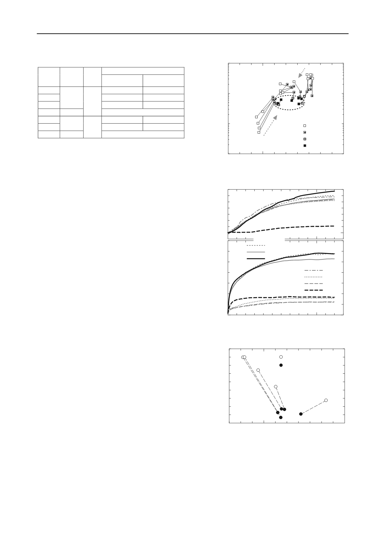
Figure 7 shows changes in
e
and
G
vh
in freeze-thaw cycles at
v
=10 kPa for five specimens. The void ratios clearly converge
on the same range as in Figure 5;
G
vh
sharply decreases to lower
0.8
1.0
1.2
1.4
1.6
10
−9
10
−8
10
−7
10
−6
Freeze−thaw
: Before
: After 1 cycle
: After 2 cycles
: After 3 cycles
Void ratio,
e
Coefficient of permeability,
k
(m/s)
Sample V
Table 1. Conditions of direct box shear tests and changes in void ratio
Void ratio,
e
Test
Freeze
-thaw
cycle
v
(kPa)
After consol.
(before freezing)
Before shear
(after thawing)
DBS1
0.97
1.00
DBS2
Figure 6. Difference in direct shear test results by freeze-thaw cycle
Figure 7. Changes in
G
vh
and
e
by freeze-thaw cycles
0
1
2
3
4
5
6
0
20
40
60
0
0.2
0.4
0.6
Vertical displacement
Shear stress,
(kPa)
Horizontal displacement,
(mm)
DBS4:
DBS7:
DBS1:
DBS2:
DBS3:
DBS5:
DBS6:
Sample CL
No
Yes
Freeze−thaw
Yes
No
Yes
Yes
Yes
Freeze−thaw
H
(mm)
0.9
1.0
1.1
1.2
1.3
0
10
20
30
40
Elastic shear modulus
Void ratio,
e
Sample V
: Before freeze−thaw cycle
G
vh
(MPa)
: After freeze−thaw cycle
Figure 5. Changes in
k
and
e
by freeze-thaw cycles
0.99
1.02
Yes
DBS3
1.01
1.05
DBS4
No
12
1.01
DBS5
0.97
0.91
DBS6
Yes
0.96
0.92
DBS7
No
75
0.95


