119
        
        
          Honour Lectures /


            Conférences honorifiques


            Proceedings of the 18


            th


            International Conference on Soil Mechanics and Geotechnical Engineering, Paris 2013


          In making settlement calculations for such structures, some
        
        
          use the rules proposed by Menard and some use the elastic
        
        
          equations often with an unload-reload modulus. Those who use
        
        
          the Menard rules, use α values based on local experience and
        
        
          influenced by the ratio between the unload-reload modulus E
        
        
          r
        
        
          and the first load modulus E
        
        
          o
        
        
          . While the value of the ratio E
        
        
          o
        
        
          /E
        
        
          r
        
        
          varies within a range somewhat similar to the range of α values,
        
        
          it is not clear why one should be related to the other. The ratio
        
        
          E
        
        
          o
        
        
          /E
        
        
          r
        
        
          is influenced by the development of plastic deformation
        
        
          around the probe while the value of α is argued to be related to
        
        
          the combination of lack of strength in tension (hoop direction as
        
        
          shown in Section 7.1) and recompression process through an S
        
        
          shape curve (Fig. 8). Those who use the elastic equation
        
        
          together with an unload-reload modulus face the problem that
        
        
          the unload reload modulus is ill defined and depends in
        
        
          particular on the extent of the unloading and the stress level at
        
        
          which the unloading takes place.
        
        
          The case of the foundation of the tallest tower on Earth, the
        
        
          828m high Burj Khalifa in Dubai, UAE, is studied further to
        
        
          investigate the issue of the first load modulus and the reload
        
        
          modulus (Poulos, 2009). The Burj Khalifa weighs
        
        
          approximately 5000MN and has a foundation imprint of about
        
        
          3300m
        
        
          2
        
        
          . The foundation is a combined pile raft 3.5 m thick
        
        
          founded at a depth of about 10 m below ground level on 1.5 m
        
        
          diameter bored piles extending some 50 m below the raft. To
        
        
          predict the settlement of the tower, a number of methods were
        
        
          used including numerical simulations. For these simulations a
        
        
          modulus profile was selected from all soil data available
        
        
          including 40 PMT tests. The PMT first load modulus profile is
        
        
          shown in Fig. 20 along with the selected design profile as input
        
        
          for settlement calculations by numerical simulations. As can be
        
        
          seen the design profile splits the PMT first load modulus profile
        
        
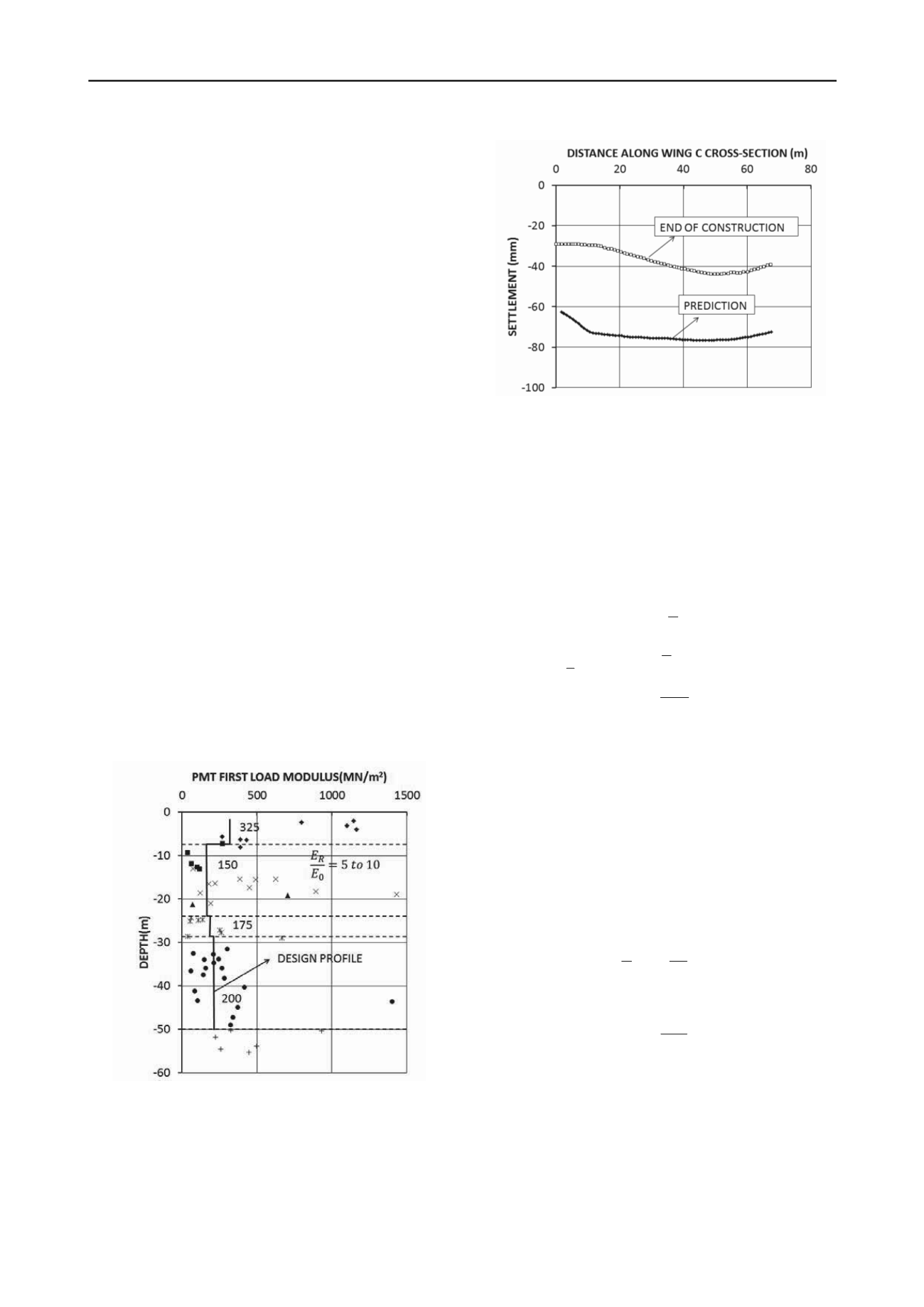
          with some conservatism. The settlement of the tower was
        
        
          predicted to be 77mm; it was measured during construction and
        
        
          reached 45 mm at the end of construction (Fig. 21). The
        
        
          reasonable comparison between measured and predicted
        
        
          settlement for this major case history gives an indication that it
        
        
          is appropriate to use the PMT first load modulus for settlement
        
        
          estimates.
        
        
          Figure 20. First load PMT modulus profile and selected design
        
        
          modulus values for the Burj Khalifa, Dubai, UAE (after Poulos,
        
        
          2009)
        
        
          Figure 21. Measured and predicted settlement of the Burj
        
        
          Khalifa, Dubai, UAE (after Poulos, 2009)
        
        
          10 DEEP FOUNDATIONS UNDER HORIZONTAL LOADS


            10.1 Single pile behavior


          For vertically loaded piles, it is common to calculate the
        
        
          ultimate capacity of the pile due to soil failure and then the
        
        
          settlement at working load. For horizontally loaded piles, an
        
        
          ultimate load due to soil failure is not usually calculated. Briaud
        
        
          (1997) proposed an equation to calculate the ultimate horizontal
        
        
          load due to soil failure for a horizontally loaded pile.
        
        
          1/4
        
        
          3
        
        
          4
        
        
          3
        
        
          3
        
        
          4
        
        
          4
        
        
          2.3


            v


            o


            v


            o


            ou


            L v


            p


            o


            o


            o


            D l


            for L l


            L D


            for L l


            H p BD


            E I


            l


            K


            K E


          (50)
        
        
          Where H
        
        
          ou
        
        
          is the horizontal load corresponding to a horizontal
        
        
          displacement equal to 0.1B, B the pile diameter, p
        
        
          L
        
        
          the PMT
        
        
          limit pressure, D
        
        
          v
        
        
          the depth corresponding to zero shear force
        
        
          and maximum bending moment, l
        
        
          o
        
        
          the transfer length, L the pile
        
        
          length, E
        
        
          p
        
        
          the modulus of the pile material, I the moment of
        
        
          inertia of the pile around the bending axis, K the soil stiffness,
        
        
          and E
        
        
          o
        
        
          the PMT first load modulus.
        
        
          In order to expand that solution to create the entire load
        
        
          displacement curve for horizontally loaded piles, it is proposed
        
        
          to first use a strain compatibility equation such that the relative
        
        
          displacement to reach the ultimate load on the pile (y/B = 0.1)
        
        
          corresponds to the relative PMT expansion at the limit pressure
        
        
          (∆R/R
        
        
          o
        
        
          = 0.41).
        
        
          0.24


            o


            y


            R


            B R


          (51)
        
        
          Then the load on the pile can be transformed into a pressure
        
        
          within the most contributing zone as


            o


            pile


            v


            H p


            BD


          (52)
        
        
          The Γ value is the ratio of the pressure on the pile divided by
        
        
          the pressure on the PMT for a corresponding set of values of
        
        
          y/B and ∆R/R
        
        
          o
        
        
          which satisfy Eq. 51. That way and point by
        
        
          point, the Γ function can be generated as a function of y/B or
        
        
          0.24∆R/R
        
        
          o
        
        
          . This approach is consistent with the approach taken
        
        
          for the load settlement curve method for shallow foundations.
        
        
          This was done for 5 piles including driven and bored piles as
        
        
          well as sand and clay soils. The piles are described in Briaud
        
        
          (1997) and in Briaud et al. (1985). They ranged from 0.3 to 1.2
        
        
          m in diameter and from 6 to 36 m in length. In each case, the
        
        
          pile dimensions were known, the load displacement curve was