122
Proceedings of the 18
th
International Conference on Soil Mechanics and Geotechnical Engineering, Paris 2013
Proceedings of the 18
th
International Conference on Soil Mechanics and Geotechnical Engineering, Paris 2013
4
2
4
2
0
y
y
y
E I
M C K y
z
t
t
(59)
where E (N/m
2
) is the modulus of elasticity of the pile, I (m
4
)
the moment of inertia of the pile against bending around the
horizontal axis perpendicular to impact, y (m) the pile
horizontal displacement at a depth z and a time t, M (kg/m) the
mass per unit length of pile (mass of pile M
p
plus mass of
associated soil M
s
), C (N.s/m
2
) the damping of the system per
unit length of pile, and K (N/m
2
) the soil spring stiffness per
unit length of pile. Note that the soil horizontal resistance is
limited to p
u
(kN/m
2
). The boundary conditions are zero
moment and zero shear at the point of impact, and zero moment
and zero shear at the bottom of the pile. The initial condition is
the displacement of the impact node during the first time step;
this displacement is equal to v
o
x Δt where v
o
is the velocity of
the vehicle and Δt the time step. Other inputs include the mass
and velocity of the impacting vehicle, and the parameters in Eq.
59 for the soil and the pile. The differential equation is then
solved by the finite difference method and it turns out that the
parameter matrix is a diagonal matrix so that no inversion is
necessary. As a result the solution can be provided in a simple
Excel spread sheet (Mirdamadi, 2013).
Because the problem is a horizontal load problem on a pile,
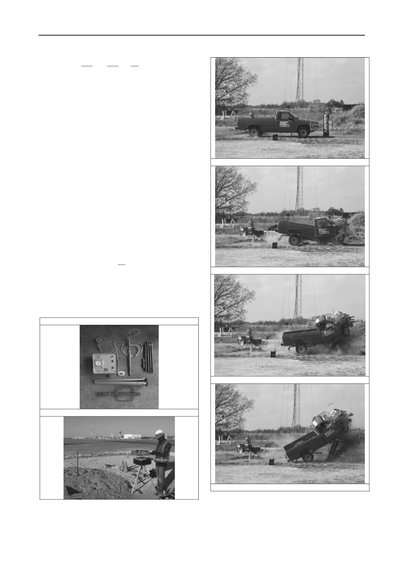
the PMT is favored to obtain the soil data. The PMT in this case
is a mini PMT called the Pencel (Fig. 30) which is driven in
place or driven in a predrilled slightly smaller diameter hole if
the soil is hard. As a result of many static and impact horizontal
load tests at various scales (Lim, 2011, Mirdamadi, 2013), the
following recommendations are made for the input parameters.
0.036
L
s
P
M B
g
(60)
2
. /
240
L
C N s m
P kPa
(61)
2.3
o
K E
and
(62)
u
p p
L
Where B is the pile width, p
L
the PMT limit pressure, g the
acceleration due to gravity, and E
o
the first load PMT modulus.
EQUIPMENT
TEST
Figure 30. Mini pressuremeter test
1
2
3
4


