3380
Proceedings of the 18
th
International Conference on Soil Mechanics and Geotechnical Engineering, Paris 2013
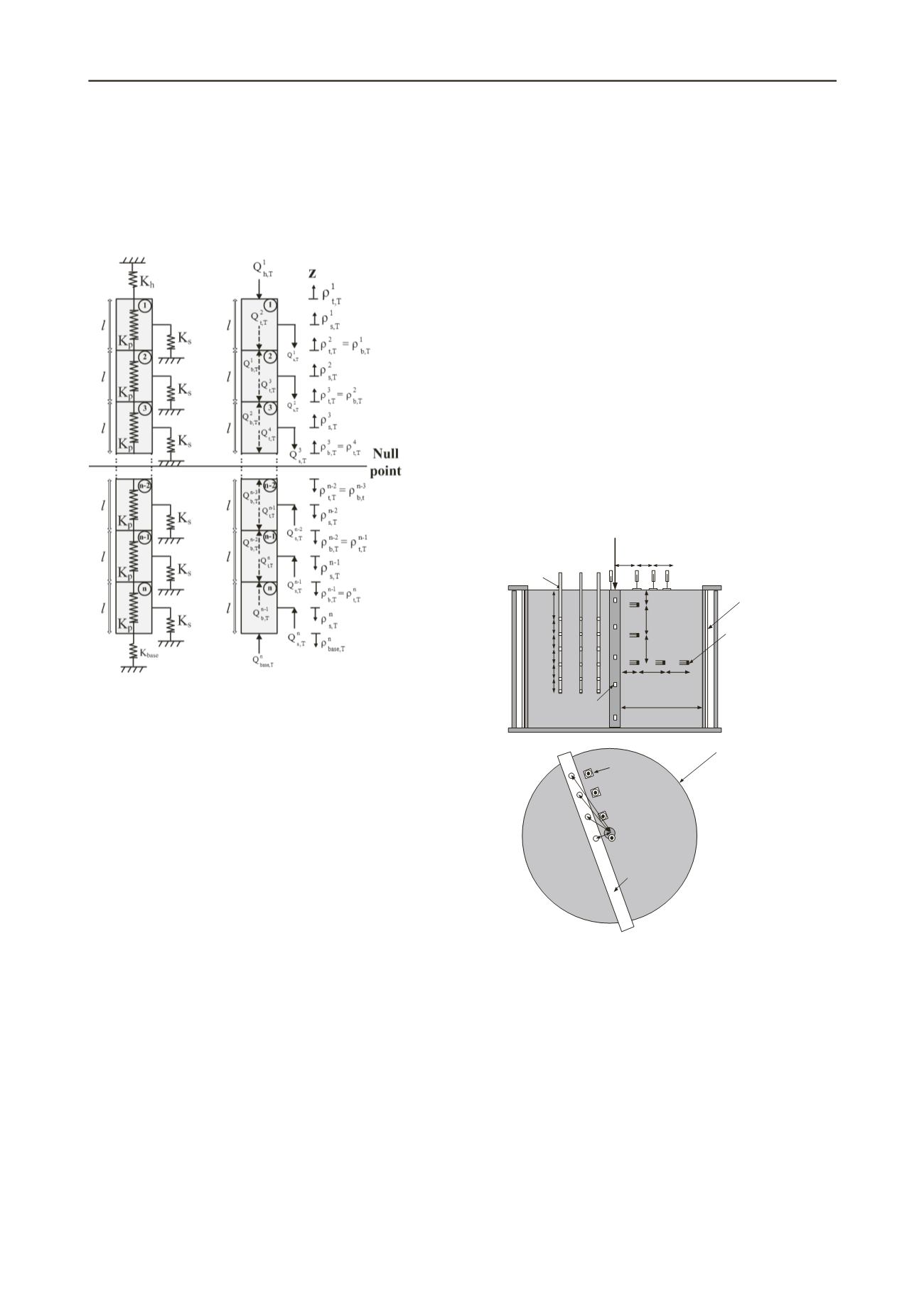
transfer analysis, a spring at the head of the foundation is used
to represent the constraint of a foundation by the overlying
building and grade beams. During heating, the foundation will
expand about a null point, the location of which depends on the
distribution of side shear values (K
s
) and the magnitude of the
end stiffness (K
base
) and head stiffness (K
h
). An iterative
approach can be used to ensure equilibrium between forces Q
and compatibility between displacements
.
Figure 1. Thermo-mechanical load-transfer analysis (Plaseied 2012)
If strain gauges are used to monitor strains in the
foundations, the thermal axial strains within a foundation can be
obtained by subtracting the mechanical strains occurring due to
an applied load (i.e., the weight of a building). Depending on
the type of strain gauge, different thermal correction factors
may need to be applied (McCartney and Murphy 2012;
McCartney and Stewart 2012). The thermal axial stresses at any
point in the foundation
T
can be defined as follows:
T
= E(
T
-
c
T)
(1)
where E is the Young’s modulus of reinforced concrete,
T
is
the measured thermalaxial strain,
c
is the coefficient of thermal
expansion of reinforced concrete, and
T is the change in
temperature. The value of
c
T represents the maximum axial
strain possible in the energy foundationfor unrestrained
conditions, and is negative (expansive) during heating.
3 FOUNDATION CASE STUDIES
3.1
Centrifuge-Scale Energy Foundation
The centrifuge-scale energy foundation evaluated in this study
has a length of 533.4 mm and a diameter of 25 mm, and was
installed in the center of a cylindrical container filled with a
layer of unsaturated Bonny silt. The base of the foundation rests
on the base of the container, providing a zero-displacement or
end-bearing bottom boundary condition. The centrifuge test was
performed at acentrifugal acceleration of 24, so the model-scale
foundation is intended to represent a prototype-scale foundation
having a length of 12.8 meters and a diameter of 1.2 meters.
Although it is understood that heat flow cannot be scaled in a
similar manner to geometry, stresses and strains, the thermally-
induced stresses and strains are governed by the restraint
provided by the surrounding soil, which depends on the stress
state. Accordingly, it is expected that the thermally-induced
stresses and strains will scale in a similar manner to mechanical
stresses and strains. Accordingly, centrifuge tests involved
maintaining the foundation at a constant temperature and
waiting for thermally induced stresses and strains to stabilize.
The model energy foundation was precast outside of the soil
layer due to the large amount of instrumentation, cables, and
heat exchanger tubing within the assembly. This also permits
the foundation to be tested outside of the soil layer to
characterize their thermal and mechanical properties. The
reinforcing cage for the model foundationwas constructed from
a hoop of reinforced wire mesh. A cardboard tube having an
inside diameter of 50.8 mm was used as a form for the
foundation, permitting a concrete cover of 5 mm on the sides
and 12.7 mm on the top and bottom. A total of three heat
exchanger loops (3 inlets and 3 outlets) was installed in the
foundation so that the distribution of heat across its
circumference would be as uniform as possible. Embedded
strain gauges and thermocouples were attached to the
reinforcement cage of the model foundation at the locations
shown in Figure 2. Linearly-variable deformation transformers
were used to measure the axial displacement of the foundation
and the soil surface. The distribution in temperature was
measured using thermocouple profile probes and dielectric
sensors (also used to monitor changes in volumetric water
content of the soil). Additional details of the instrumentation are
presented by McCartney and Stewart (2012).
Figure 2.Schematics of the centrifuge-scale energy foundation test
A comprehensive set of characterization tests were
performed on the pre-cast drilled shaft outside of the soil in a
load frame at 1-gravity to determine the mechanical and thermal
properties of the reinforced concrete. These results from these
tests are reported in detail by Stewart (2012). The first test
involved application of incremental axial loads under room
temperature conditions, taking care to properly level the
foundation and center the load to avoid bending. The
mechanical strains encountered during application of an axial
load of 700 kPa were variable. The Young’s modulus
determined using the corrected strain data was 7.17 GPa. The
foundation was then heated to a temperature of 62 °C by
circulating fluid through the heat exchange tubes within the
foundation while maintaining a constant axial stress of 439 kPa.
The foundation was permitted to freely expand under this axial
stress, permitting definition of the coefficient of linear thermal
expansion of the foundation (
c
= -7.5
/°C, where
is
micro-strain, with compressive strain defined as positive).


