3381
Technical Committee 307 + 212 /
Comité technique 307 + 212
Heating tests were performed on the energy foundation in
the layer of Bonny silt (USCS classification of ML) compacted
at a gravimetric water content of 14% to a dry density of
1451 kg/m
3
. An axial stress of 384 kPa was applied to the head
of the foundation using a feedback-controlled electric motor.
This motor permits the load to be maintained constant but
permits free displacement. This implies that the value of K
h
for
the centrifuge-scale foundation should be close to zero. A heat
pump, operated outside the centrifuge, was used to control the
temperature of the fluid being circulated through the scale-
model foundations. Details of the heat control system are
provided by Stewart (2012).
3.2
Full-Scale Energy Foundations
Two drilled shaft foundations installed as part of the new
Denver Housing Authority senior residential facilitywere
converted into energy foundations. The energy foundations
were coupled into a conventional GSHE system which was
already being incorporated into the building. This paper focuses
on the results of one of the drilled shafts,having a length of 14.8
meters and a diameter of 0.91 meters, that includes 3 heat
exchanger loops. The shaft consists of a full-length reinforcing
cage with nine #7 vertical reinforcing bars tied to #3 lateral
reinforcing hoops spaced 0.36 meters on center. A schematic of
the drilled shaft within the soil profile is shown in Figure 3. The
drilled shaft functioned as rock-socketed, end-bearing elements
in bedrock, with an expected load of 3.84 MN.The grade beams
attached to the top of the foundation likely provided a non-zero
stiffness to the head of the foundation (K
h
> 0).
Foundation A
FILL
SAND
AND
GRAVEL
CLAYSTONE
(Denver Blue
Shale)
FINISHED GRADE
3 Heat Exchanger
Loops
3.8 m
2.0 m
2.1 m
4.6 m
3.0 m
2.2 m
2.1 m
2.1 m
1.1 m
0.91 m
dia.
14.8 m
Vibrating
wire strain
gauge
locations
3 heat
exchange
loops
Figure 3.Soil stratigraphy and layout of foundation instrumentation
At the site, urban fill extends from grade to a depth of
approximately 3 meters and consists of slightly moist, medium
dense, clayey sand with gravel. Beneath the fill, non-expansive,
medium dense, silty, sand and gravel extended to a depth of
approximately 7.6 meters below grade. Following the sands and
gravels, the subsurface conditions consisted of hard sandy
claystone bedrock from the Denver formation. Because of the
potential for caving during drilling through the overburden and
possible perched ground water conditions, a cased-hole method
was chosen for installation of the drilled shaft foundations at the
site. Groundwater was observed near the depth of the claystone.
The heat exchanger system in the energy foundation consists
of 44 mm-diameter polyethylene tubing attached to the inside of
the reinforcing cages. The drilled shaft contains a total of 82.3
linear meters of tubing configured into three loops running the
length of the reinforcing cage. The heat exchanger tubing was
routed along the inside perimeter of the reinforcing cage to
avoid crossing the diameter of the cage, which could block
concrete flow or cause segregation of concrete. Equal angular
spacing of the tubing was maintained to ensure relatively
uniform temperature along the circumference of the shafts. Six
vibrating wire concrete-embedment strain gauges with attached
thermistors were incorporated into the foundation to monitor
temperature and axial strain distributions with depth, although
one gauge was damaged. The supply and return temperatures of
the heat exchanger fluid were also monitored. More information
is provided by McCartney and Murphy (2012).
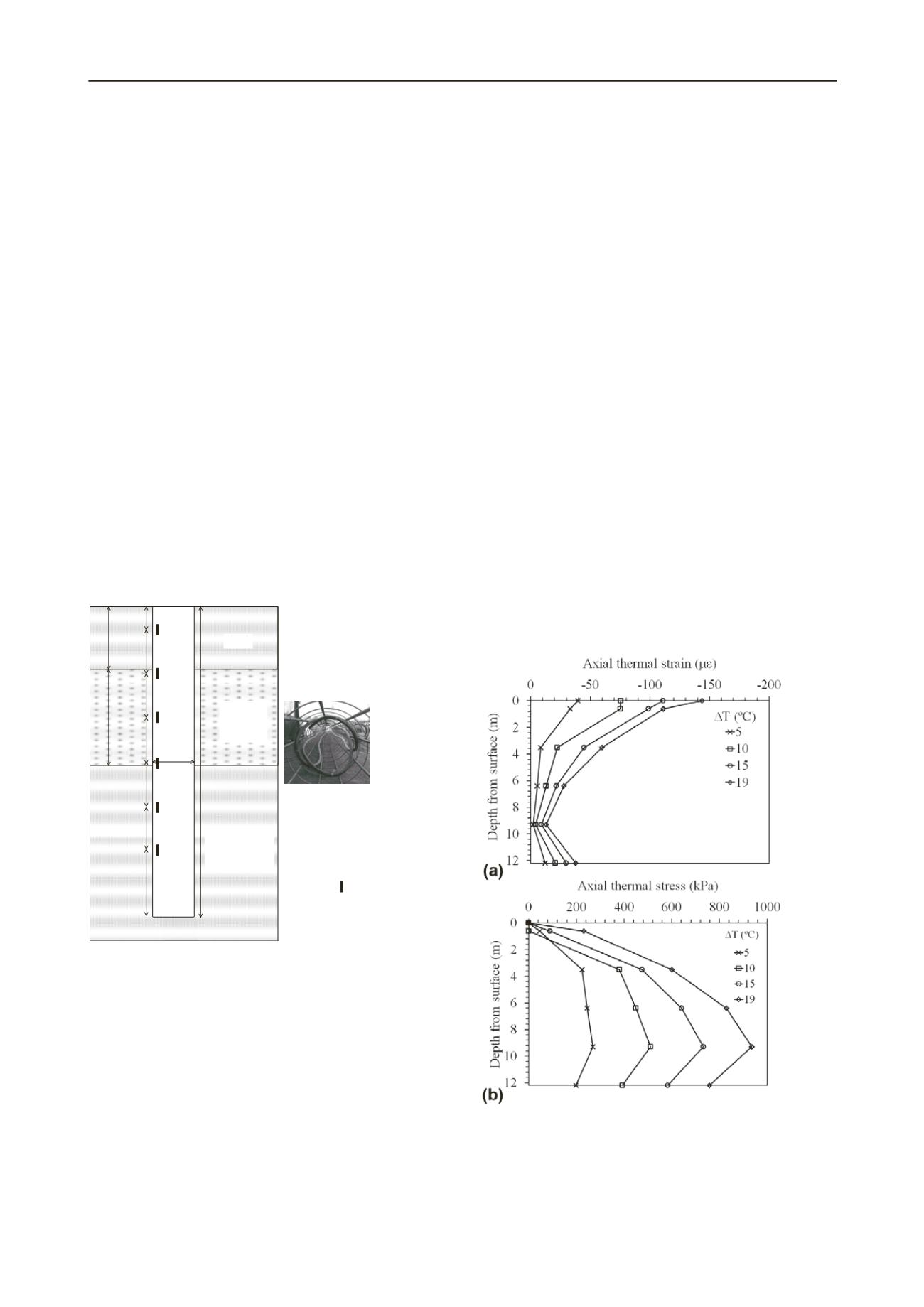
4 STRAIN DISTRIBUTIONS
4.1
Centrifuge-Scale Energy Foundations
The axial thermal strain distributions in the centrifuge-scale
energy foundation after heating to different changes in
temperature above the ambient temperature of 20
°
C are shown
in Figure 4(a). Heating leads to a relatively uniform increase in
negative axial strain throughout the foundation, indicating
thermal expansion. The smallest strains are located near the toe
of the foundation, which is as expected due to the rigid end
restraint. The axial strains at the very top of the foundation
represent the thermal strain for free expansion of the foundation
(
c
T). The measured strains are consistent with these
theoretical values, and confirm that the top of the foundation
can expand freely. An upward displacement in prototype scale
of 1 mm was observed. The thermal axial stresses were
calculated from the thermal strains using Equation 1. The
location of minimum strain (and maximum stress) reflects the
null point for the foundation, which is approximately at the
bottom of the foundation. The trend in stress approaches zero at
the top of the foundation, supporting the conclusion that K
h
= 0.
Figure 4. Centrifuge results: (a) Axial strains; (b) Axial stresses
4.2
Full-Scale Energy Foundations
During operation of the heat pump between March and May
2012, the temperature of the foundation was relatively uniform,
and involved both heating and cooling. The strains induced in
the foundation during different average changes in foundation
temperature are shown in Figure 5(a). Similar to the centrifuge-


