3253
Technical Committee 307 /
Comité technique 307
3 CONSTRUCTION PROCEDURE AND
INSTRUMENTATION.
The walls construction process was conducted using the moving
formwork technique, which is a common method for the
construction of wrapped-faced walls in the field. In order to
reduce the side wall friction, the whole internal walls of the test
facility were covered with three polypropylene sheets
interspersed with lubrication (liquid silicone).
Three walls sections were named according to their cardinal
orientation as West, Central and East. This configuration allows
for the instrumented portion of the wall (Central section) to
approach a plane-strain condition, free from side wall effects, as
far as practical. This procedure has been adopted at Royal
Military College of Canada (RMC) in a successful long-
standing program on construction of full-scale reinforced walls
(Santos et al. 2010).
The construction procedure consisted of placing the backfill
material and compacting it in 200mm lifts. In order to provide a
light compaction and a satisfactory surface leveling, a manual
compaction roll was used. Near to the face, a hand tamping
cylinder was used to minimize the effects of the compaction on
the facing displacements. The total construction time was 29
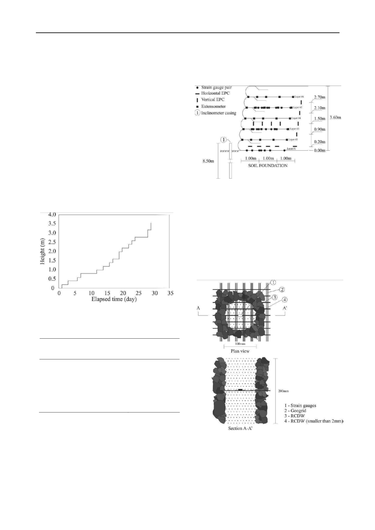
days. Figure 4 and Table 3 present RCDW reinforced walls
construction history and their main characteristics.
Figure 4. RCDW reinforced walls construction history (Santos et al.
2010).
Table 3. Main walls characteristics.
Value
Characteristic
Wall #1
Wall #2
Geosynthetics
Geogrid Geotextile
Height (m)
3.60
Facing batter (°)
13
Reinforcement spacing (m)
0.60
Reinforcement length (m)
2.52
Approximately 400 instruments were installed in the two
walls in order to record the following:
a. strain in reinforcement layers (strain gauges and wire-
line extensometers installed in wall #1 and wall #2,
respectively);
b. wall face displacements;
c. vertical earth pressure at the base of the RCDW (earth
pressure cells - EPC);
d. horizontal earth pressure within the RCDW mass
(EPC);
e. settlements along the surface of the RCDW mass
(superficial marks);
f.
horizontal displacement of the foundation soil
(inclinometer).
Figure 5 shows the instrument distribution profile.
Figure 5.Instruments distribution profile.
Additional procedures were necessary to protect the
instruments devices against mechanical damages during the
walls construction. Because of the presence of coarse grained
particles (Figure 2), the installation of the instrumented geogrid
layers and earth pressure cells (EPC) were carried out using fine
grained particles around the instruments. PVC tubes were used
to create a region with selected fine RCDW - smaller than 2mm
around EPC and strain gauges. Figure 6 presents a scheme of
the region around strain gauges after geogrid layer installation
process.
Figure 6.Region around strain gauges (wall #1).
The data recording after the walls construction revealed that
just one strain gauge was mechanically damaged, which
correspond to a survival level of 98% for installed strain gauges.
This survival level kept stable until the end of research program
even though the rainy seasons in Brasília. It was observed that
all EPC survived to installation process but not to the first rainy
season. After 110 days, all EPC failed.
Outward displacements of the walls faces during
construction were measured. It was observed for the wall #1


