3261
Technical Committee 307 /
Comité technique 307
2003).
Th
result of consolidation. Also the foundation
set
ty and for settlement stress
is shown
ation should to
ndation; b)
Ex
t important aim is to decrease the volume of
d with
ring and first of all
st.
used for better protection against floods.
Th
The degree of compaction can significantly determine
e final result – what is for example very important from the
the scale 1:1 (see Figure 7) proved
extremely high resistivity against surface erosion and such
reinforced dikes can be applied not only for reconstructed parts
but also in selected sections of dikes, where the crest is little bit
lower than other part and overflowing can start there as higher
resistivity is guaranteed.
Figure 4. Remediation by in situ reactive barriers
So it means that buildings constructed in the 1950´s- 1960´s
are now often demolished and reconstructed. Many of these
large modern buildings have been designed with wide column
spacing necessitating the use of deep piles or piled raft
foundations, as was the case e.g. for London, (Chow
erefore the discussion is about three options – avoid, remove,
reuse. The last option is now preferred as reuse of old
foundations has many positive aspects from the environmental
point of view, (e.g. Butcher, Powell and Skinner 2006).
Nevertheless we can reuse also spread foundations, which
were used for old dwellings, e.g. prefab panel buildings; for
farm buildings as well as for old industrial structures. Although
the price for removal is not as problematic there as for pile
foundations, the version of reuse is very attractive. Here the
bearing capacity for subsoil composed of clays increased with
time as the
tlement induced by new loading can be rather low, as some
additional structural strength had chance to develop there with
time for particle arrangement given by stresses from the old
foundations.
Direction of the new research activity is therefore connected
with observation of changes with time not only in subsoil
surrounding existing foundations but also at the contact with
this foundation. For bearing capaci
and strain paths are more complicated. Schematic drawing what
is going on for selected layer below spread foundation
in Figure 5 and new laboratory and filed investig
prove some expected assumptions.
Figure 5. a) Scheme of vertical stresses below spread fou
pected settlement by additional loading ∆σ
2
2
UTILIZATION OF LARGE VOLUME WASTE
Human activities produce a huge amount of different waste.
Therefore the mos
such waste. Nevertheless for remaining waste the strategy
should be defined and more efficient way is connecte
reutilization of this waste. Civil enginee
geotechnical engineering has a great chance to reuse large
volume waste as:
-
Construction – demolition waste – old bricks, concrete,
ceramics, old asphalt pavement, gravel balla
-
Industrial waste – ash, dross, slag;
-
Mining waste – overlaying soils, waste rock, quarry
waste, residues after washing china clay…
During last period the orientation is also on other relatively
large volume materials as tyres, glass, polystyrene…
Only one example will be shown, which is combining the
utilization of waste for the production of new construction
material which can be
is new construction material is called brick – fibre – concrete
which is composed from old bricks and concrete crushed
particles together with classical additives for concrete – cement
and water and with new additives – with synthetic fibres,
(Vodička et al 2009).
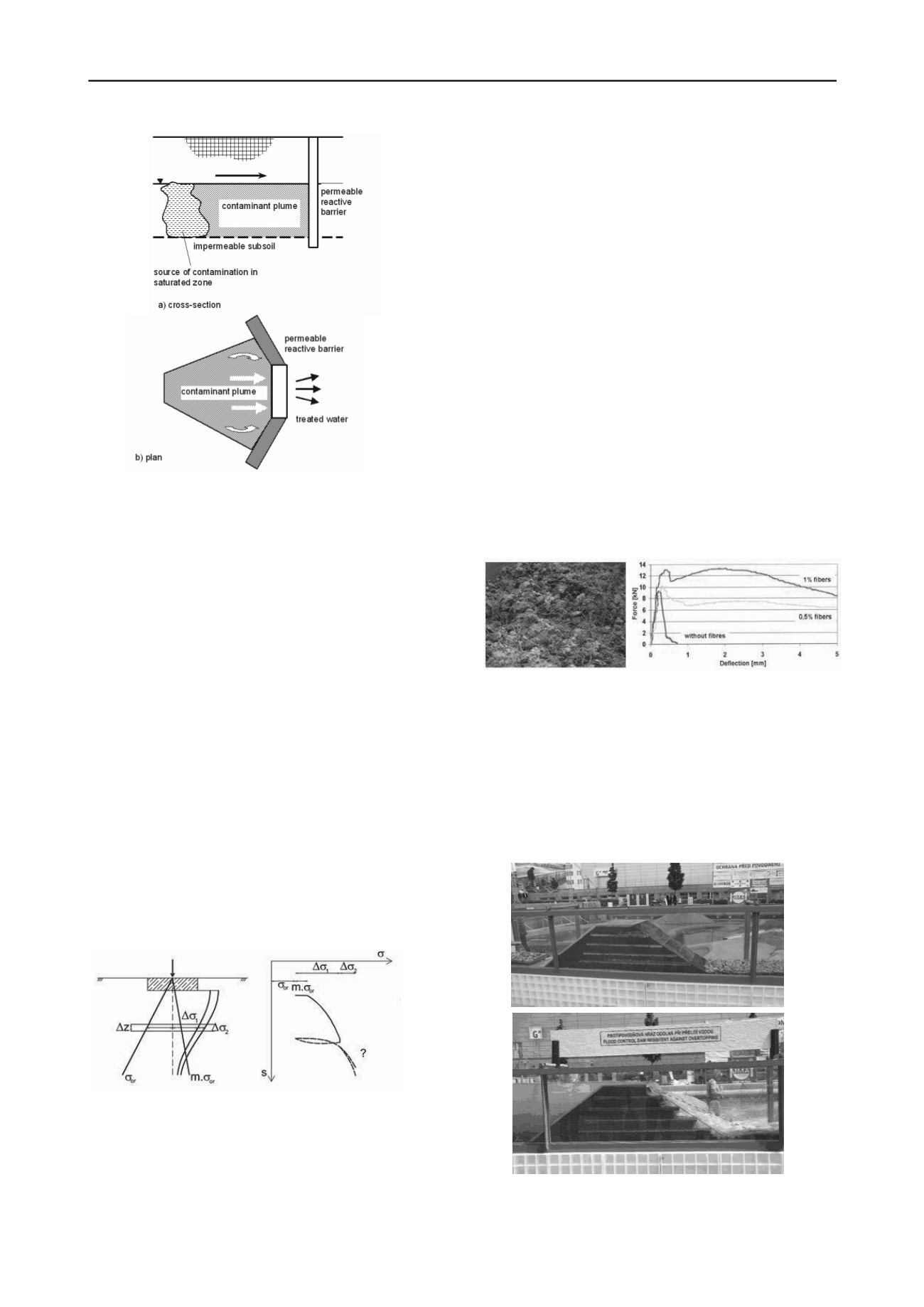
After mixing together the final product looks like on the
Figure 6a, where interconnection of individual components is
visible.
th
view of permeability, as this property can be guaranteed in
relatively wide range. The impact of the fibers can be seen from
the Figure 6b, representing the result of bending test of prepared
beam.
Figure 6. a) Mixture of brick – fibre – concrete; b) Influence of
synthetic fibres on the strength parameters and behaviour after failure
After heavy floods there is usually huge amount of the
construction and demolition waste and the new product can be
applied for the reinforcement of reconstructed part of dikes.
Laboratory models up to
Figure 7. Model of reinforced dike before and after the test


