 
          3213
        
        
          Technical Committee 307 /


            Comité technique 307


            Eurocode 1


            Actions on Structures


          Normative Handbook (blended text)
        
        
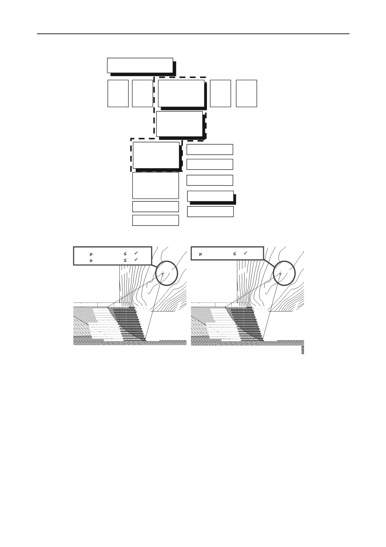
          Figure 3.  Normative  range designing with geosynthetics (according to Kempfert, 2011)
        
        
          Figure 4.  Example of a calculation of a steep geogrid reinforced slope, using BS 8006 (left) and EBGEO (right) with the same parameter set except
        
        
          partial factors according to the used Design Approach (according to Klompmaker & Werth, 2011)
        
        
          also low strains less than 1.5 %. The strain therefore is less as
        
        
          expected by Ultimate Limit State Design (ULS), but in
        
        
          accordance to scientific approaches and actual understanding of
        
        
          compound material (Heerten et al., 2009).
        
        
          Ruiken et al. (2010) managed to visualize the shear rotation
        
        
          of granular material in the front of a reinforced wall. The
        
        
          required deformation of the facing is very low and is depending
        
        
          on the degree of reinforcement respectively the vertical layer
        
        
          distance of the reinforcement. Secondary shear planes develop
        
        
          during deformation, showing significant differences as to be
        
        
          expected by active earth pressure theory. EBGEO has already
        
        
          used these findings on the basis of the publication by
        
        
          Pachomow (2007), allowing for a reduced earth pressure on the
        
        
          facing of a reinforced earth wall.
        
        
          From back analysis of the constructions documented by
        
        
          Herold (2007), taking the actual design codes into
        
        
          consideration, general conclusions can be drawn and
        
        
          recommendations for further design are given concerning the
        
        
          expected deformation of a construction, see Table 1.
        
        
          4 WORKED EXAMPLES FOR INFRASTRUCTURE
        
        
          DESIGN USING HIGH STRENGTH GEOGRIDS
        
        
          The high ductility of reinforced soil structures and its economic
        
        
          benefit have raised a certain increase of usage in the last decade
        
        
          in Europe. Vollmert et al. (2010) document a structure, using
        
        
          approx. 6 ha of geosynthetics for noise barrier walls and
        
        
          embankments on weak subsoil in the Netherlands. Fig. 5 gives
        
        
          an partial overview of the construction with a total length of
        
        
          2 km. The costs of the geosynthetics used are less than 1% of
        
        
          the total budget.
        
        
          The visible and to environmental influences exposed part of
        
        
          the construction is the facing. Several facing types as gabions,
        
        
          wrap-around method as well as concrete blocks and panels are
        
        
          commonly used.
        
        
          0.35
        
        
          0.40
        
        
          0.40
        
        
          0.45
        
        
          0.45
        
        
          0.50
        
        
          0.50
        
        
          0.55
        
        
          0.55
        
        
          0.60
        
        
          0.65
        
        
          0.70
        
        
          0.75
        
        
          0.80
        
        
          0
        
        
          0.
        
        
          0.95
        
        
          pv=20.00
        
        
          Geos1/µ:0.90/T0:40.0/mxT:40.0
        
        
          Geos2/µ:0.90/T0:40.0/mxT:40.0
        
        
          Geos3/µ:0.90/T0:40.0/mxT:40.0
        
        
          Geos 4/µ:0.90/T0:40.0/mxT:40.0
        
        
          Geos5/µ:0.90/T0:40.0/mxT:40.0
        
        
          Geos6/µ:0.90/T0:40.0/mxT:40.0
        
        
          Geos7/µ:0.90/T0:10.0/mxT:20.0
        
        
          Geos 8/µ:0.90/T0:10.0/mxT:20.0
        
        
          Geos9/µ:0.90/T0:10.0/mxT:20.0
        
        
          Geos10/µ:0.90/T0:10.0/mxT:20.0
        
        
          Geos11/µ:0.90/T0:10.0/mxT:20.0
        
        
          Geos12/µ:0.90/T0:10.0/mxT:20.0
        
        
          Geos13/µ:0.90/T0:10.0/mxT:20.0
        
        
          Geos14/µ:0.90/T0:10.0/mxT:20.0
        
        
          Geos15/µ:0.90/T0:10.0/mxT:20.0
        
        
          y=7.00m;L=7.00m
        
        
          y=7.70m;L=7.00m
        
        
          y=8.40m;L=7.00m
        
        
          y=9.10m;L=7.00m
        
        
          y=9.80m;L=7.00m
        
        
          y=10.50m;L=7.00m
        
        
          y=11.20m;L=7.00m
        
        
          y=11.90m;L=7.00m
        
        
          y=12.60m;L=7.00m
        
        
          y=13.30m;L=7.00m
        
        
          y=14.00m;L=7.00m
        
        
          y=14.70m;L=7.00m
        
        
          y=15.40m;L=7.00m
        
        
          y=16.10m;L=7.00m
        
        
          y=16.80m;L=1.50m
        
        
          Geos2/µ:0.90/mxt:131.17T :4 .0/mxT:40.0/
        
        
          Geos3/µ:0.90/mxt:121.29T0:4.0/mxT:40.0/
        
        
          Geos4/µ:0.90/mxt:111.42/T0:4.0/mxT:40.0/
        
        
          Geos5/µ:0.90/mxt:101.5 T:40.0/mxT:40.0/
        
        
          Geos6/µ:0.90/mxt:91.67T :4.0/mxT:40.0/
        
        
          Geos7/µ:0.90/mxt:81.80T0:1 .0/mxT:20.0/
        
        
          Geos8/µ:0.90/mxt:71.93/T0:1 .0/mxT:20.0/
        
        
          0.99


            =


            E


            d


            /


            R


            d


            = 0.99


            1.0


            Limit State, STR, DA3 = A2 + M2 + R3


          (STR: structural failure)
        
        
          0.35
        
        
          0.40
        
        
          0.40
        
        
          0.45
        
        
          0.45
        
        
          0.50
        
        
          0.50
        
        
          0.55
        
        
          0.55
        
        
          0.60
        
        
          0.65
        
        
          0.70
        
        
          0.75
        
        
          0.80
        
        
          0
        
        
          0.
        
        
          0.95
        
        
          pv=20.00
        
        
          Geos1/µ:0.90/T0:40.0/mxT:40.0
        
        
          Geos2/µ:0.90/T0:40.0/mxT:40.0
        
        
          Geos3/µ:0.90/T0:40.0/mxT:40.0
        
        
          Geos 4/µ:0.90/T0:40.0/mxT:40.0
        
        
          Geos5/µ:0.90/T0:40.0/mxT:40.0
        
        
          Geos6/µ:0.90/T0:40.0/mxT:40.0
        
        
          Geos7/µ:0.90/T0:10.0/mxT:20.0
        
        
          Geos 8/µ:0.90/T0:10.0/mxT:20.0
        
        
          Geos9/µ:0.90/T0:10.0/mxT:20.0
        
        
          Geos10/µ:0.90/T0:10.0/mxT:20.0
        
        
          Geos11/µ:0.90/T0:10.0/mxT:20.0
        
        
          Geos12/µ:0.90/T0:10.0/mxT:20.0
        
        
          Geos13/µ:0.90/T0:10.0/mxT:20.0
        
        
          Geos14/µ:0.90/T0:10.0/mxT:20.0
        
        
          Geos15/µ:0.90/T0:10.0/mxT:20.0
        
        
          y=7.00m;L=7.00m
        
        
          y=7.70m;L=7.00m
        
        
          y=8.40m;L=7.00m
        
        
          y=9.10m;L=7.00m
        
        
          y=9.80m;L=7.00m
        
        
          y=10.50m;L=7.00m
        
        
          y=11.20m;L=7.00m
        
        
          y=11.90m;L=7.00m
        
        
          y=12.60m;L=7.00m
        
        
          y=13.30m;L=7.00m
        
        
          y=14.00m;L=7.00m
        
        
          y=14.70m;L=7.00m
        
        
          y=15.40m;L=7.00m
        
        
          y=16.10m;L=7.00m
        
        
          y=16.80m;L=1.50m
        
        
          Geos2/µ:0.90/mxt:131.17T :4 .0/mxT:40.0/
        
        
          Geos3/µ:0.90/mxt:121.29T0:4 .0/mxT:40.0/
        
        
          Geos4/µ:0.90/mxt:111.42/T0:4.0/mxT:40.0/
        
        
          Geos5/µ:0.90/mxt:101.5 T:40.0/mxT:40.0/
        
        
          Geos6/µ:0.90/mxt:91.67T :4 .0/mxT:40.0/
        
        
          Geos7/µ:0.90/mxt:81.80T0:1.0/mxT:20.0/
        
        
          Geos8/µ:0.90/mxt:71.93/T0:1.0/mxT:20.0/
        
        
          0.99


            C1:


            =


            E


            d


            /


            R


            d


            = 0.86


            1.0


            C2:


            =


            E


            d


            /


            R


            d


            = 0.99


            1.0


            Limit State, STR, DA1,


            Combination 1 (C1) = A1 + M1 + R1


            Combination 2 (C2) = A2 + M2 + R1


          EC 5
        
        
          EC 6


            EC 7-1:


            DIN EN 19971-1


            Geotechnical Design


            - General Rules


            National Annex:


            DIN EN 1997-1/NA


            DIN 1054:2010


            Supplementary


            Rules to


            DIN EN 1997-1


          DIN 4084:2009-1
        
        
          Soil – Calculation of
        
        
          Embankment Failure
        
        
          […]
        
        
          DIN XXXX
        
        
          DIN YYYY
        
        
          EAU
        
        
          EAB
        
        
          expected for 2011
        
        
          EC 8 EC 9


            ….


          EA-Pfähle (Piles)


            EBGEO


          …