3110
Proceedings of the 18
th
International Conference on Soil Mechanics and Geotechnical Engineering, Paris 2013
Braking time t [sec]
F
[N]
E*
b
F = m a
max
B= m v =
F
max
2
t
Impulse :
Braking distance
[m]
v
[m/s]
Braking time t [sec]
Braking time t [sec]
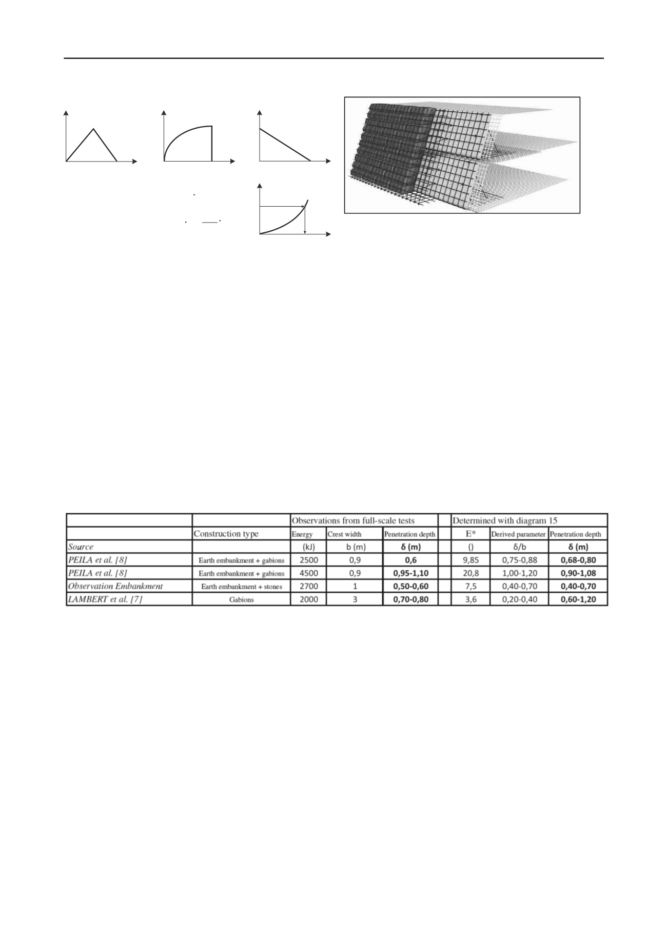
Figure 5. Assumptions for the evaluation (a = deceleration)
Figure 6. Inspectable outer facing-system (double-wall-system) to protect
the load-bearing structure built using the wrap-around method (System
NAUE DW)
5 COMPARISON OF DESIGN MODEL WITH FULL-SCALE
TESTS
4.5
Structure configuration
The constructive aspects of rockfall-protection embankments are
just as important as their numerical design. Rockfall incidents
inevitably result in damage and wear on the facing. If at all
possible, the facing should therefore effectively protect the outer
surface of the reinforced earth body; it should also require little
maintenance and ideally allow inspection, in case partial damage
requires repair (ONR 24810 (2013) und ÖNORM B 1997-1-1
(2007)).
If rockfall-protection embankments are constructed as
reinforced-soil bodies with steep side slopes, the reinforced body
must have a wrap-round front surface to guarantee adequate
anchorage for individual reinforcing layers at the edge of the
structure. A facing is required to protect the structure against UV
and impact. Figure 6 shows an example of a slim gabion solution
which allows inspection and can be built independently of the
supporting embankment body. The thickness, the area weight of
the protective layer, and the quality of the steel elements must
reflect the anticipated stressing/loading.
The results of model testing form the basis for the application of
the results to full-size construction. To investigate the applicability
of the design proposal, it will be necessary to evaluate existing
protection embankments and the damage observed to have
resulted from rockfall. This means that, after an incident, at the
very least the block size and the penetration depth will have to be
documented. Additionally, the velocity will have to be back-
calculated using a rockfall-impact simulation program. The
diagram in Figure 4 was confirmed at least by the full-scale tests
of Peila et al. (2007), Lambert et al.(2011), and the observations of
protection embankments in Tirol and Voralberg. The comparisons
of observations on actual structures with the results obtained using
the design proposals are summarised in Table 4. It can be seen that
there is very good agreement.
Table 4: Comparison of full-size tests with design proposal
9
REFERENCES
Blovsky S. (2002). Reinforcing possibilities with geosynthetics
Dissertation. Technische Universität Wien. Institut für Grundbau- und
Bodenmechanik.
Hofmann R. und Mölk M. (2012). Bemessungsvorschlag für
Steinschlagschutzdämme. Geotechnik 35, Heft 1, Verlag Ernst &
Sohn.
Labiouse V. and Heidenreich B. (2009). Half-scale experimental study of
rockfall impacts on sandy slopes. - Nat. Hazards Earth Syst. Sci. 9,
pp. 1981–1993.
Lambert S., Heymann A. and Gotteland P.(2011). Real-scale experimental
assessment of cellular rockfall protection structures. Proceedings
interdisciplinary workshop on rockfall protection – ROCEXS,
Innsbruck 2011.
ONR 24810 (2013). Technischer Steinschlagschutz – Begriffe,
Einwirkungen, Bemessung und konstruktive Durchbildung,
Überwachung und Instandhaltung(Technical protection against
rockfall –Terms and definitions, effects of actions, design, monitoring
and maintenance) Entwurf, Ausgabedatum: 2013-01-01.
Peila, D., Oggeri, C. and Castiglia, C. (2007). Ground reinforced
embankments for rockfall protection: design and evaluation of full
scale tests. Landslides 4, pp. 255-265.
ÖNORM B 1997-1-1 Eurocode 7 - Entwurf, Berechnung und Bemessung
in der Geotechnik - Teil 1 (2007). Allgemeine Regeln - Nationale
Festlegungen zu ÖNORM EN 1997-1 und nationale Ergänzungen.
Pichler B., Hellmich C., and Mang H. (2005). Impact of rocks onto gravel
– design and evaluation experiments. – International Journal of Impact
Engineering 31, pp. 559-578.
Plassiard J.P. and Donze F.V. (2010). Optimizing the design of rockfall
embankments with a Discrete Element Method. Engineering
Structures, 32, pp. 3817-3826.


