3101
Technical Committee 301 /
Comité technique 301
Orographically the BLT terrain is located in a mid-mountain
relief zone with 650-800 maltitude drop. Within the area next to
the survey terrain Esto-Sadok and East-Achikhinsky fault zones
occur. The South-Esto-Sadok fault passes at the south of the
surveyed zone close to the “Bean Storage Area”. One of the
feathering faults, occurring from north-west to south-east,
passes across the northern end of the designed trough. The
massif is water-logged via aquifer zones all the way down to the
investigated depth, the water heads correlate with the cut depths
through the surface valley due surface flows of the
Shumikhinsky stream.
Geological slope cuts are mainly represented by high density
gravely clay loam or by gravely soils with clay loam fill. The
clay loams and clay loam fills feature liquid-plastic to hard
consistency.
At 16-40 m depths the quaternary deposits are underlain by
low-strength argillites. Depending on the water table the
argillites and their fills feature liquid plastic to hard consistency.
The seismicity of the construction project location is 8.5
points as per micro-seismic zoning.
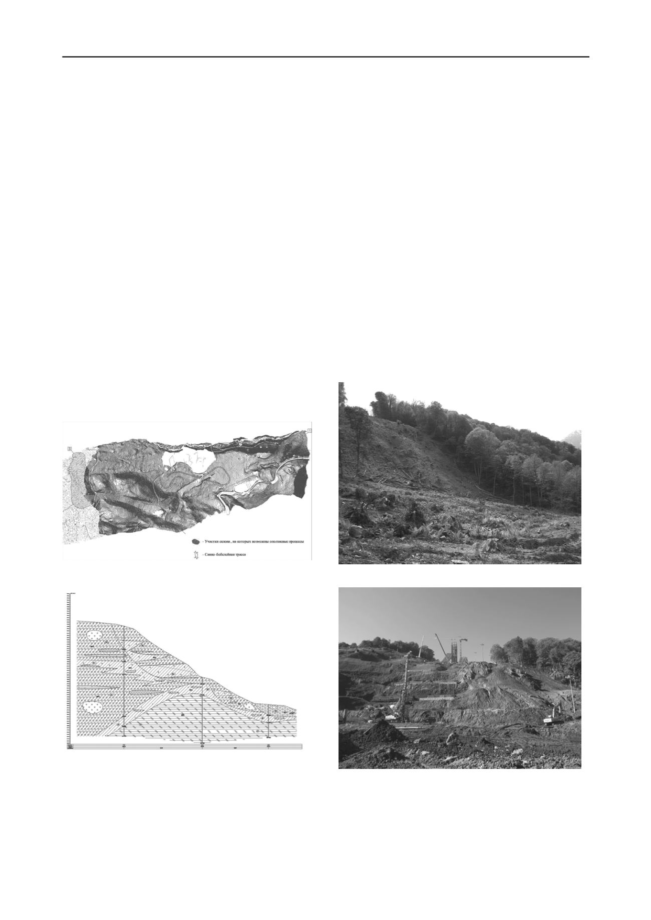
The survey identified three slope terrains, on which
development of landslide processes is possible under design
seismic action. In order to confirm slope instability the authors
performed verification analysis of the above-mentioned slope
terrains with the help of PLAXIS as they were and in the case of
BLT structures erection. According to the analytical results the
stability factor was below the admissible level of 1.1 for 8.5
points seismic action(Figs. 4, 5).
Fig. 4. Topographic map of BLT terrain. Black domains - landslide
prone zones; the curved line - bobsleigh/luge track
Fig. 5. Land-slide prone slope cross section at terrain 1
Then the authors proposed measures to provide for the
required values of stability factor i.e., to erect retaining walls of
various configurations, depending on the internal forces in them
(one or two rows of bored piles, groups of bored tangent piles
with the stiff pile capping beam).
Herein, application of piles as counter-slide structures shall
be discussed. Spaced piles, located as a row across a slope
would not let soil move between them at whatever landslide
pressure (the effect of “non-pushing through”, Fedorovsky,
2006) with the critical clearing between piles being larger the
greater is the internal friction angle. However, the drawback of
such pile strengthening consists in that the bending forces in the
piles are so high that often surpass their bending strength.
Therefore, in difficult cases the bending moments are reduced
by respective measures (pile heads anchoring), or the piles
stiffness or strength are increased (larger diameter up to 1.5 m)
or installation of buttresses or several piles instead of single
piles. In this case there were proposed bored tangent piles with a
strong pilework on top. Bored secant piles with dedicated
reinforcement are more effective.
Pile walls along the slope feature one more advantage. If
their spacing across the slope is less than the wall length then
the active (landslide) soil pressure is, as a rule, less than that of
the ultimate thrust (Nazarova et al., 1995). The above structures
were widely applied for the next facility, discussed below.
5. SKI-JUMP COMPLEX
The complex of К-125 and К-95 ski-jumps geological
environment is similar to that of BLT, however, the altitude
drops are greater, but hydro-geological situation is better.As
different from BLT the counter-slide structures are partly
combined with footings of the proper ski-jumps, of the landing
slope, of the start and the referee towers.
Fig. 6. Ski-jump site at the beginning of construction operations
Fig. 7. The same terrain during footing erection
This is due to some factors. Firstly, the initial slope (Fig. 6)
has k
st
= 1.04 for soil design parameters while k
st
1.0 for
seismic conditions. The ski-jump track is located in a cut 8…10
m deep that undercuts the side slopes and deteriorates the
landslide situation (Fig. 7).
In order to overcome these difficulties buttress rows of 3…5
of 0.88 m dia bored secant piles were selected, with some of


