3100
Proceedings of the 18
th
International Conference on Soil Mechanics and Geotechnical Engineering, Paris 2013
Fig. 2. Gravely clay soil
At the initial stage gravely soil strength parameters were
determined indirectly from results of crushing dry soil in a
pebble mill (DalNIIS technique, 1989). Then the obtained
parameters were corrected, because the natural slope stability
analyses yielded faulty results (slope stability factor k
st
1).
Later the obtained experience made it possible to correlate the
values of soil strength parameters with soil composition and
state and thus to identify essential errors.
Essential reduction of soil shear resistance after moistening
was a specific feature of the terrain. The relief usually prevented
long-term moistening by torrents and/or melting snow.
However, soil strength parameters variation had to be taken into
account in stability analysis as an action.
Seismicity is yet another special action. Design seismicity of
the terrain is reportedly from 8 to 9 points. In the analyses the
seismic acceleration was generally assumed to be horizontal,
but in some cases a more unfavorable direction had to be taken
into account i.e., at 30° versus the horizon.
3. KRASNAYA POLYANA – ROZA-KHUTOR ROAD
Research and technological support of the motor road project
was the authors’ first effort. Therefore, the basic analytical and
design concepts were tested on this very project.
The first soil data was obtained by DalNIIS method (1989)
and initially looked dubious. It was especially so for gravel and
pebble soils with clay fill, for which internal friction angle was
23.8° and 26.6°, cohesion 13.6 kPa and 11.3 kPa respectively.
For coarse-grain soils the values of
were evidently
underestimated. This fact was proved by natural slope stability
analysis. For some road cross sections the value of k
st
with
characteristic values of
c
and
dropped down below 1.0 and
even below 0.8.
This was demonstrated after two stability analyses: by the
method of variable level of shear-strength mobilization
(MVLM)
,
proposed by the authors (Fedorovsky, Kurillo, 1998,
2001), and by finite elements analysis (Brinkgreve, Vermeer,
1998). Both methods MVLM and FEM (PLAXIS) yielded close
k
st
values that were much lower than those obtained with the
well-known Bishop, Morgenstern-Price and Janbu methods,
applied by the surveyors. This fact demonstrates that the new
methods are certainly better for the analysis of essentially
heterogeneous soils. The new methods are also more accurate,
as is shown by comparing solutions of problems, having exact
solutions (such as bearing capacity problems).
After
and
c
of the two above-mentioned soils were
corrected to 36°, 32.6° and 16.4 kPa, 19.7 kPa respectively, all
the analyzed sections yielded stability factor slightly over 1.
This was due to the fact that in the least stable sections the
critical slip-lines passed through these very two engineering
geological elements..
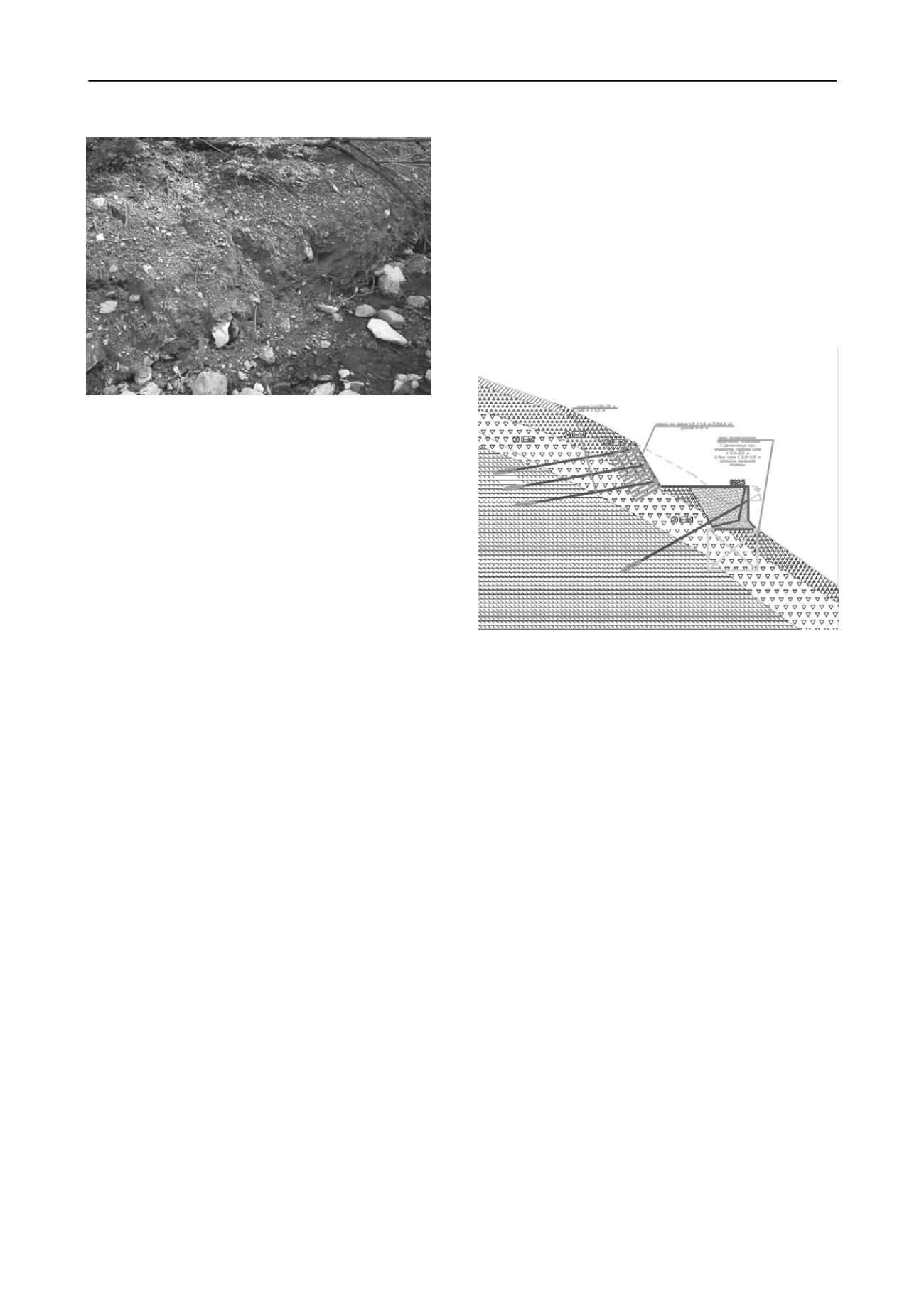
The road is constructed by cutting into the rock massif and
sometimes by filling soil and by enlargement toward the lower
slope. The objective was to select such strengthening solution
for the upper and the lower slopes that would ensure the
minimum value of k
st
, at least 1.15,for the main load (including
10 kPa load on the road proper) and 1.05 for the special
(seismic) load. Where necessary, the upper slope was to be
retained by anchors, inserted into the primary rock (argillite). In
order to minimize the impact on the natural environment the
upper slope retaining wall was made rather steep (60° versus the
horizon) and 8…16 m high. In order to ensure adequate
stiffness and strength of the slope plane 6..8 m long soil nails
were proposed (Fig. 3).
Fig. 3 Counter-landslide structures for the motor road.
Where the lower slope fill is insignificant, no extra measures
were required. However, at some locations an angle-shaped
retaining wall, strengthened by a row of anchors, was to be
erected. However, it was insufficient for one of the cross-
sections, as the wall was supported by soft soil. It was proposed
to replace the soil by broken stone fill or to strengthen it by
grouting (рис. 3).
Notably, application of anchors “neutralizes” both local
landslides of the upper and lower slopes along with the global
ones, initiated above the road and ending below it.
The anchors were directly simulated in PLAXIS (with the
account of transfer from 3D to 2D). In MVLM method the
plane, to which the anchors are fixed, is loaded to simulate
stressed anchor action on the slope. Both methods demonstrated
that the pulling force, applied to 2.5 m spaced anchors (along
the road), per 4 m along the slope is 40…45 tons.
Just a few words on seismic numeric simulation. Russian
standards recommend to apply proportional inertia forces to soil
weight with
AK
1
factor. Here
A
depends on the terrain seismic
intensity(
А
= 0.2 for magnitude 8), and
K
1
depends on allowable
soil deformations. If a soil slope is viewed as a structure with
limited (landslide) deformations then
K
1
= 1. If then the road
subgrade is considered separately from the counter-slide
structures and the plastic non-destructive deformations of the
structure are allowed then
K
1
= 0.25. Finally, it is only logical to
assume (geometrical) mean value of
K
1
=
1·0.25 = 0.5, even
more so that the result coincides with recommendations of
Eurocode 8.
4. BOB-SLEIGH/LUGETRACK
This project was more difficult than theprevious one due to
considerable relief altitude drops and to diverse hydrogeological
conditions.
Bobsleigh/luge track (BLT) is located in the lower part of the
Aibga ridge northern slope near Krasnaya Polyana.


