 
          3109
        
        
          Technical Committee 301 /


            Comité technique 301


          is required to prevent the sphere rebounding over the
        
        
          embankment crest on the first impact.


          The maximum width of the activated embankment body
        
        
          is 5 to 6 times the sphere diameter.


          In the tests it was found that the failure planes from the
        
        
          second impact onwards tended increasingly to form in
        
        
          an upward direction.


          The pictures taken with the high-speed camera clearly
        
        
          show quite significant elastic deformations during the
        
        
          period of impact.
        
        
          45
        
        
          70
        
        
          =10°
        
        
          D
        
        
          v
        
        
          v
        
        
          =20°
        
        
          b=4,5cm
        
        
          e
        
        
          h
        
        
          a
        
        
          „Uphill face"
        
        
          „Downhill face"
        
        
          Extensometer
        
        
          Extensometer
        
        
          a , a , a , a
        
        
          o
        
        
          2 3
        
        
          1
        
        
          b
        
        
          o
        
        
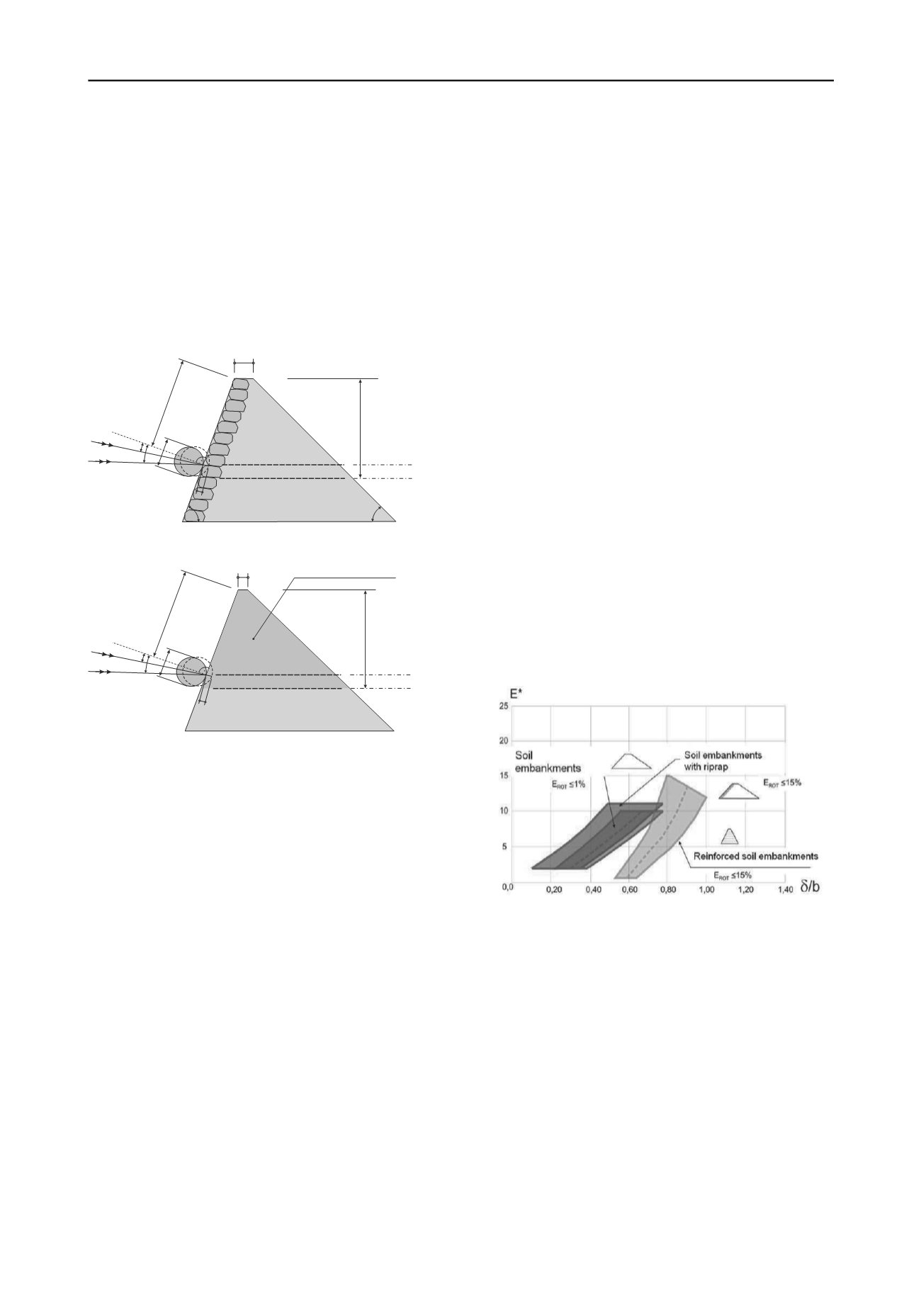
          Figure 2. Model embankment with rip-rap facing
        
        
          =10°
        
        
          D
        
        
          v
        
        
          v
        
        
          =20°
        
        
          e
        
        
          h
        
        
          a
        
        
          "Uphill face"
        
        
          „Downhill face"
        
        
          Extensometer
        
        
          Extensometer
        
        
          a , a , a , a
        
        
          o
        
        
          2 3
        
        
          1
        
        
          b
        
        
          o
        
        
          Activated embankment area A
        
        
          a
        
        
          b
        
        
          Figure 3. Model embankment system


            3.2.3 Lessons from trials with rip rap facing and without


            geosynthetics


          The following additional observations were made on
        
        
          embankments with rip rap facing:


          Slope angles ≥ 50° require a freeboard of at least 1 x the
        
        
          diameter of the sphere.


          After the impact, the sphere scarcely changes its height,
        
        
          whereas in the case of pure soil embankments, and
        
        
          reinforced structures, it tends to jump or roll in the
        
        
          direction of the crest.


            3.2.4 Lessons learned from the tests with geosynthetics


          The model tests with the geosynthetics all showed a
        
        
          significantly larger lateral distribution (influence width)
        
        
          of the displacements. An influence width of at least 8 - 9
        
        
          times the diameter of the sphere can be estimated from
        
        
          the measurements and the pictures taken with the high-
        
        
          speed camera.


          Very slim constructions with uphill and downhill slope
        
        
          angles of 70° and 60° were also investigated. These
        
        
          exhibited a noticeably more elastic behaviour than pure
        
        
          soil embankments.


          However, they require a markedly greater freeboard than
        
        
          embankments with rip rap facing. For geogrid-
        
        
          reinforced structures, a freeboard of 1.5 times the sphere
        
        
          diameter can be considered as being on the safe side.
        
        
          4 DESIGN MODEL FOR ROCKFALL-PROTECTION
        
        
          EMBANKMENTS
        
        
          4
        
        
          .1


            Principles


          A characteristic failure body for different structures was derived
        
        
          from the 1g model tests. An important and consistent parameter
        
        
          was the activated width of the embankment in the direction normal
        
        
          to the impact. The basic concept of the proposed design method is
        
        
          to derive a non-dimensional relationship between the penetration
        
        
          depth and the crest width (δ/b) using the relative impact energy
        
        
          E*, Hofmann & Mölk (2012).
        
        
          4.2


            Activated failure body


          Normal to the impact direction, the size of the activated failure
        
        
          body is a function of the embankment structure. Whereas the
        
        
          width of the failure body in unreinforced embankments (both with
        
        
          and without rip rap facing) is at least 5 to 6 times the diameter of
        
        
          the block (the sphere in the model), this value increases to 8 to 9
        
        
          times the diameter of the block for reinforced structures.
        
        
          4.3


            Required freeboard


          Freeboard is defined here as the distance between the upper
        
        
          surface of the block and the upper surface of the embankment,
        
        
          measured along the slope (Section 3.2)
        
        
          Figure 4. Comparison of the different structures
        
        
          4.4


            Estimate of the equivalent static force


          An estimate of the equivalent static force is made using equation
        
        
          (5), on the assumption that the force initially increases, and then
        
        
          decreases, in a linear manner, and that the velocity decreases in a
        
        
          linear manner according to Blovsky (2002) (Figure 5). The
        
        
          equivalent static force is then distributed over the activated
        
        
          embankment width involved.
        
        
          F = v² m / δ
        
        
          (5)
        
        
          F = 2 v m / Δt
        
        
          (6)
        
        
          Δt = 2 δ/ v
        
        
          (7)
        
        
          δ = (0,8 bis 0,85) m v²/ F
        
        
          (8)