2582
Proceedings of the 18
th
International Conference on Soil Mechanics and Geotechnical Engineering, Paris 2013
clamp sinking, the constant strain rate or the fixed rate of load
increase (similar to ISO 10319:2008) with relative error
indications of breaking load ± 1.0 %, with absolute error
indications of elongation ± 1.0 mm, with an average rupture
duration regulated from (30±15) to (60±15) sec.
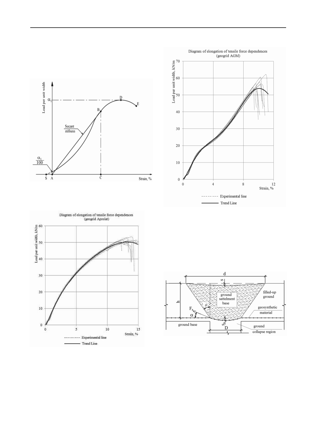
Figure 2. Typical load-elongation curve.
In practice, we had to build these relationships using the
results obtained with the help of the tensile-testing machine that
provided the constant rate of bottom clamp sinking (Fig. 3, 4).
Figure 3. Example of elongation-load curve according to the test results.
Figure 4. Example of elongation-load curve according to the test results.
The obtained dependences were used in the calculations
done with the help of both numerical methods (PLAXIS
program) and the developed technique.
3 TECHNIQUE OF REINFORCED SOIL BASE
CALCULATION
The design scheme of the proposed method is shown in
Figure 5.
Figure 5. Design diagram of reinforced ground settlement under earth
collapse.
In this method the following assumptions allowing to use
formulas well-known in soil mechanics for the calculation of
stresses in ground bases were made:
the reinforced ground mass is in an equilibrium (stabilized)
state before the ground collapse formation;
– the reinforcing layer is located in the homogeneous
ground;
– the stress-strain state is considered at that moment when
the marginal state of the ground mass is reached;
the deformation form of the ground mass above the
reinforcing interlayer has a sectional view of a trapezoid;
the geosynthetic material does not stretch beyond the
collapse region;
the arch effect is not taken into account.


