2392
Proceedings of the 18
th
International Conference on Soil Mechanics and Geotechnical Engineering, Paris 2013
Proceedings of the 18
th
International Conference on Soil Mechanics and Geotechnical Engineering, Paris 2013
The bending stiffness of the model pile is similar to a scaled
prototype steel pile, however, the behaviour of the pile during
loading also depends on the stiffness of the surrounding soil.
According to Poulus and Hull (1989) a pile behaves flexible if
and rigidly if
/3
, where
is a critical length
defined by Eq. 1.
is the bending stiffness of the pile and
is Youngs modulus of elasticity of the soil.
= 4.44
.
(1)
Due to the low stresses in the soil at 1g small scale testing,
the stiffness is also low. From previous testing and numerical
modelling an estimated soil stiffness of 4 MPa can be used for
the sand in the test setup (Roesen et al. 2010). With use of Eq. 1
the model pile is thereby found to behave rigidly during lateral
loading. In comparison a prototype steel monopile with
= 5
m and
= 0.07
m installed in sand with
E
s
= 70 MPa
is found to behave rigidly with a slenderness ratio
/ = 3
and behave flexible with
/ = 9
. Thus, for the examined
slenderness ratio (
/ = 5
) the model pile experiences a more
rigid behaviour than the prototype pile. Nevertheless, the results
obtained in the small scale model tests can be used as
underlying basis for understanding the monopile behaviour
during lateral cyclic long-term loading.
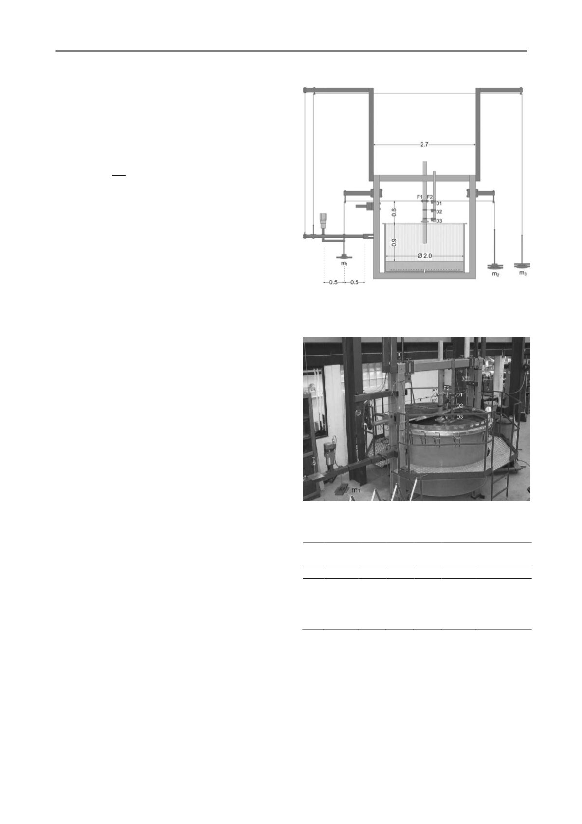
The test setup consists of a cylindrical sand container with an
inner radius of 2.00 m and a height of 1.20 m surrounded by a
loading frame equipped for both static and cyclic loading. The
setup is an improvement of the system presented in Roesen et
al. (2012) which originally is based on the setup presented by
LeBlanc et al. (2010). A cross-sectional sketch and a photo of
the system are shown in Figure 1 and 2. The pile is installed in
the middle of the container by use of a mechanical motor with
installation velocity of 0.02 mm/s. The container holds up to
0.90 m dense saturated sand with 0.30 m highly permeable
gravel underneath. In the bottom a drainage system with
perforated pipes ensures homogeneous in- and outflow of water.
The cyclic loading system is a simple load controlled system
based on a lever arm, weight hangers with applied masses,
,
, and
, wires, and an electric motor controlling the
rotation of weight
. The rotation causes an oscillating motion
on the lever and thereby a cyclic loading on the pile. The system
is thereby capable of providing sinusoidal loading to the pile for
more than 60 000 load cycles. The rotational frequency of the
motor is set to 0.1 Hz to be in agreement with environmental
wave loading (Peng et al. 2006).
Initially, when the mass
=
= 0
,
the mass
is
chosen to outbalance the system. Depending on the weights
chosen for
and
the system is capable of providing both
one- and two-way loading with varying
and
, i.e. different
direction, amplitude, and mean loading level. The loading is
applied through steel wires attached to the pile 600 mm above
soil surface. Hence, the pile experiences both horizontal and
moment loading. In both sides of the pile a HBM U2A 100 kg
load cell is attached measuring the actual force applied to the
pile throughout the whole test. The displacement of the pile is
measured using three WS10-125-R1K-L10 displacement
transducers from ASM GmbH. The transducers,
1
,
2
, and
3
are mounted 600 mm, 375 mm, and 155 mm above soil
surface, respectively. The rocking rotation,
, and displacement
of the pile at soil surface is found by use of linear regression of
the three measurements assuming rigid pile behaviour. The data
sampling rate is 2 Hz.
Before conducting any cyclic tests a static loading test is
performed. The static test is conducted displacement controlled
by use of a motor with a loading rate of 0.02 mm/s. The
displacement is actuated 600 mm above soil surface, i.e. the
same height as the loading in the cyclic loading tests. The pile is
loaded to a rotation of 2°, unloaded, and reloaded to failure. The
static test is used as a reference for the ultimate lateral
Figure 1. Sketch of the test setup. F1 and F2 refer to the two load cells,
D1, D2, and D3 refer to the three displacement transducers and m
1
, m
2
,
and m
3
, refer to the weights applied on the load hangers. All
measurements are in meters.
Figure 2. Test setup for cyclically long-term loaded monopiles.
Table 2. Test programme with relative soil densities,
, loading
characteristics, and number of cycles,
.
Test
No.
Type
(%)
Static test after
cyclic loading
1
Static
78.56
-
-
-
-
2
Cyclic
87.76
0.18
0.03
50 894
yes
3
Cyclic
85.38
0.24
0.10
51 732
no
4
Cyclic
87.87
0.25
-0.01
50 960
yes
5
Cyclic
91.70
0.36
0.03
60 224
yes
resistance and the maximum resistance obtained is interpreted
as the ULS load on the pile.
In total four long-term cyclic loading tests are performed,
each with more than 50 000 load cycles. The tests are conducted
with
=
, i.e. one-way loading with the target
= 0. The
magnitudes of the loading in the cyclic tests are chosen to
reflect realistic loading conditions for FLS and SLS loading,
which according to LeBlanc et al. (2010) is approximately 30%
and 40% of the ultimate limit state loading (ULS), respectively.
Thus, the target maximum moment applied in the cyclic loading
tests are defined as 20%, 25%, 30% and 40% of the maximum
static lateral resistance, i.e.
is chosen in the interval 0.2 to
0.4. In Table 2 a summary of the testing programme with the
obtained loading characteristics is presented.


