2309
Technical Committee 209 /
Comité technique 209
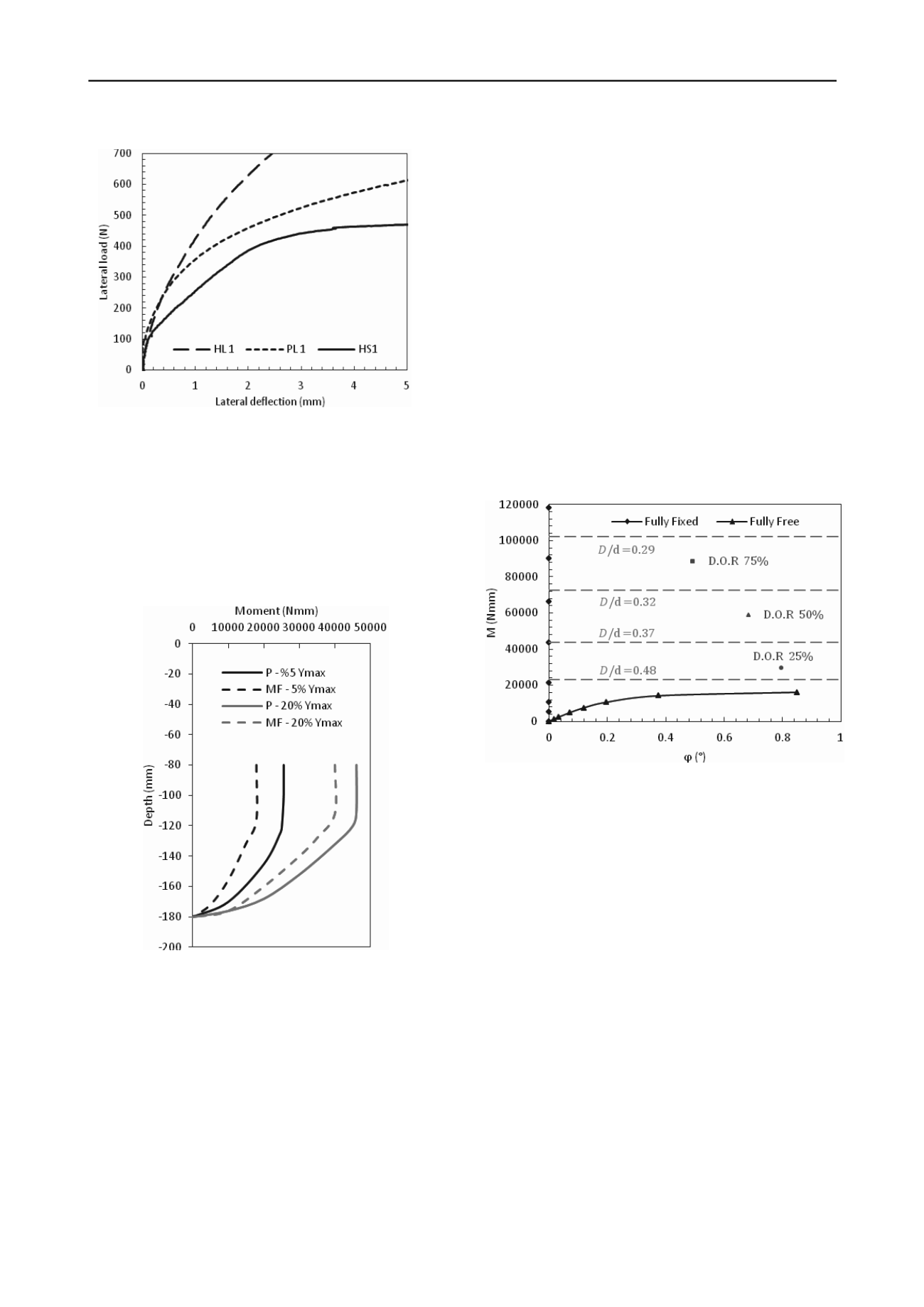
Figure 4. Load deflection graph for centrifuge tests carried out on the
hybrid system (after Stone
et al.
2011).
In Figure 5, the bold lines represent the bending moments at
5% and 20% of the maximum deflection for the pile only case
and the dashed lines show the behaviour of the hybrid system.
The results show that adding the footing to the pile reduces the
bending moment at any given deflection, and as a result
increases the moment capacity of the system at any given
applied lateral load. The results indicate about 25%
improvement in the bending moment for at both deflections.
Figure 5. Bending moment distribution along the pile length for the
hybrid system.
3. ANALYSIS
Whilst some advanced numerical modelling of monopiled
footings has been undertaken (El-Marassi
et al
. 2008; Stone
et
al.
2010; Arshi
et al
. 2011; Arshi and Stone 2012), the method
presented here utilises conventional lateral pile analysis
methodology where the hybrid system is idealised to a lateral
pile with a resisting moment applied at the mudline. The
resisting moment capacity provided by the footings were
estimated analytically using conventional bearing capacity
theory and applied at the mudline acting in the oposite dirtection
to the loading. This approach only considers the ultimate
condition of the system and does not allow the moment
developed by the footing to be generated as a function of the
footing rotation.
The results generated by this approach are illsutetared in
Figure 6 where it is shown how different pile to footing
diamater increses the moment capacityof the piles, where this
variation lies between a fully free and a fully fixed pile.
The dashed lines in Figure 6 show the ultimate moment
capacities of the hybrid system. Although this method
successfully leads to obtaining the ultimate load bearing
capacity of the hybdegree of rigidity (D.O.R 75%, 50% and
25% showing the the ultimate capacity of the system when
%75, 50% and 25% of the ultimate moment at pile head is
applied to the free headed pile) of the system are shown as a
benchmark for comparing how differenet pile to footing
diameters relate to the fully fixed moment. As apparent in
Figure 6, increasng the sie of the footing tends to increse the
lateral load bearing capacity. As the footing size increases, it
gets close to the fully fixed head condrion. This also indicates
that there for a given pile diamater and length, there ought to be
a footing size afterwhcih increseing the footing size further will
not enhance the lateral load bearing capacity of the foundation
system.
Figure 6. Moment vs. rotation plot for the hybrid system with different
pile to footing ratios.
In addition to this, design charts have been developed which
relate the pile embedment length to pile and footing diameters.
Numerous design charts have been developed covering a wide
range of pile diameters, pile lengths, footing diameters and
normalized moment capacities an example of which is shown in
Figure 8 where the L/D ratios vary from 1 to 10 and the footing
to pile diameter ratios varies from 0 to 1. The moment capacity
of the hybrid system has been normalised and is shown against
footing to pile diameter ratio. The lines in between represent
different pile embedment depth where for a given moment
capacity the designer could utilise this graph to choose the
appropriate pile length as well as pile and footing diameters. It
is also notable that for any given value of normalized moment
capacity the designer has the option of choosing a short pile
relatively large footing diameter, or long pile with relatively
small footing diameter. The flexibility in this design approach is
beneficial in particular designing the hybrid system in difficult
soil conditions.


