2299
Technical Committee 209 /
Comité technique 209
pipe distortion and over-stress irrespective of the sea bed soil
type. A less discussed cause of large displacement is where a
pipeline crosses a seismic fault; here it is movement of the
ground with respect to the pipe that causes gross distortion.
Fault crossings occur both onshore and offshore.
The geotechnical analysis for large displacement requires
suitable tools and numerical models and both have developed
significantly in recent years. A variety of large displacement
numerical methods with 3D capability are commercially
available for design purposes. Similarly, constitutive models
for soft clay that account for competing strain rate and strain
softening effects, and competing pore pressure generation and
dissipation, are available for designers. Specific numerical
elements to model the large displacement interaction between a
pipe and the surrounding soil are also currently under
development for practical application in design (SAFEBUCK
JIP). However, the constitutive and numerical modeling for
large displacement in dense sand is less well advanced.
Pipe buckling and pipe walking is usually assumed to occur
between fixed seabed structures. There may be scope for
permitting the seabed structures to move horizontally to help
accommodate axial pipe displacement.
Several of these topics are described in four papers to the
discussion session.
3.1
Dynamic embedment of offshore pipelines
Dutta et al (2013) examine pipe laying and dynamic embedment
using Coupled Eulerian Legrangian (CEL) methods available in
ABAQUS software. Progressive degradation of undrained shear
strength with plastic shear strain is included using the model of
Einav and Randolph (2005). Similar analysis by Wang et al
(2010) used remeshing and small strain (RITSS analysis).
The simplified problem is illustrated in Figure 11. A pipe is
penetrated monotonically into a soft clay sea bed under self-
weight (submerged weight of pipe). The pipe is then cycled
laterally by a displacement u/D = ± 0.05, in the x direction of
Figure 11, under constant self-weight vertical load. This causes
additional pipe penetration.
(Dutta et al 2013)
Figure 11. Pipe penetration of a seabed.
The analysis uses the same dimensions, soil parameters and
loading sequence as the first stage of two pairs of centrifuge
tests by Cheuk and White (2008) on a light and heavier pipe.
The progressive pipe penetration and magnitude of horizontal
resistance caused by cyclic lateral displacement is computed.
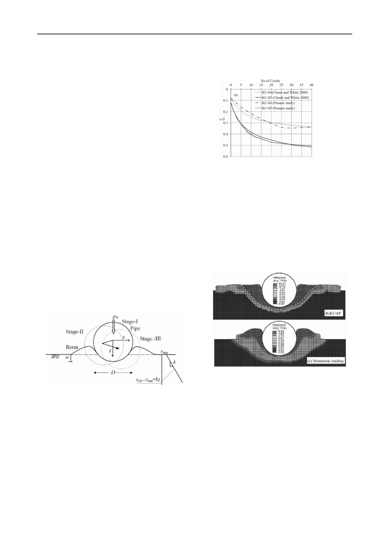
The penetration of the pipe with cycles of lateral displacement
is shown in Figure 12 for one pair of pipe tests.
Current practice is to estimate separately the embedment due
to pipe laying and due to dynamic effects. The initial
embedment on pipe laying involves temporary overload at the
touch down point. Typically the pipe weight is increased by a
“lay factor” and the initial pipe penetration under monotonic
loading is computed for this higher load. The effect of small
amplitude cyclic lateral motion is incorporated using a
“dynamic embedment factor” that multiplies up the initial
monotonic pipe lay embedment to determine a final estimated
pipe embedment. The centrifuge tests and analysis here did not
incorporate initial overloading of the pipe, but the forty cycles
of lateral loading resulted in a dynamic embedment factor of the
order 4 to 5, within the range often assumed in practice.
(Dutta et al 2013)
Figure 12. Static and dynamic pipe penetration of a seabed.
As shown previously by Wang et al (2010), the analysis
provides insight into the size of the zone of highly sheared and
softened soil around the pipe and the shape of the berms formed
by pipe penetration. The results in Figure 13 are for the heavier
pipe and show dynamic pipe penetration and monotonic pipe
penetration to the same depth (increased vertical load). The
comparison is striking. Dynamic embedment causes more
extensive plastic strain softening in the soil, coloured red, and
wider and flatter berms than generated by monotonic pipe
penetration. The latter could be important for the analysis of
initial lateral breakout of the pipe. Dynamic embedment affects
the magnitude of pipe penetration, the zone of soil remoulding
and the shape of the berms formed.
(Dutta et al 2013)
Figure 13. Dynamic and monotonic pipe penetration of a soft seabed.
3.2
Pipeline fault crossing
Damage is caused to pipelines that cross a seismic fault that
subsequently displaces. Rupture of oil or gas pipelines can
cause fire and environmental risk. For critical pipelines, the
magnitude and direction of localized fault displacement should
be assessed and appropriate engineering implemented to avoid
pipe rupture due to ground movement.
Moradi et al completed centrifuge tests on buried steel pipe
subject to an upward thrust fault at 30
⁰
to the vertical in the
direction of the pipe. A fault displacement 70mm was applied
across an 8mm diameter buried pipe with 0.4mm wall thickness
tested in a centrifuge at 40g. In one test the pipe is simply
buried in the compacted sand. A low density and light weight
loose backfill was used in the second test. The axial and
bending strain in the pipe was measured in both tests. The light
backfill allowed the pipe to buckle and displace over a greater
length considerably reducing the damage to the pipe. The pipe
embedded in the sand suffered more localized deformation and
damage, as illustrated by the photos post testing, Figure 14.


