2297
Technical Committee 209 /
Comité technique 209
Figure 3. Thornton Bank GBS (after Peire et al 2009).
(Arroyo et al 2013)
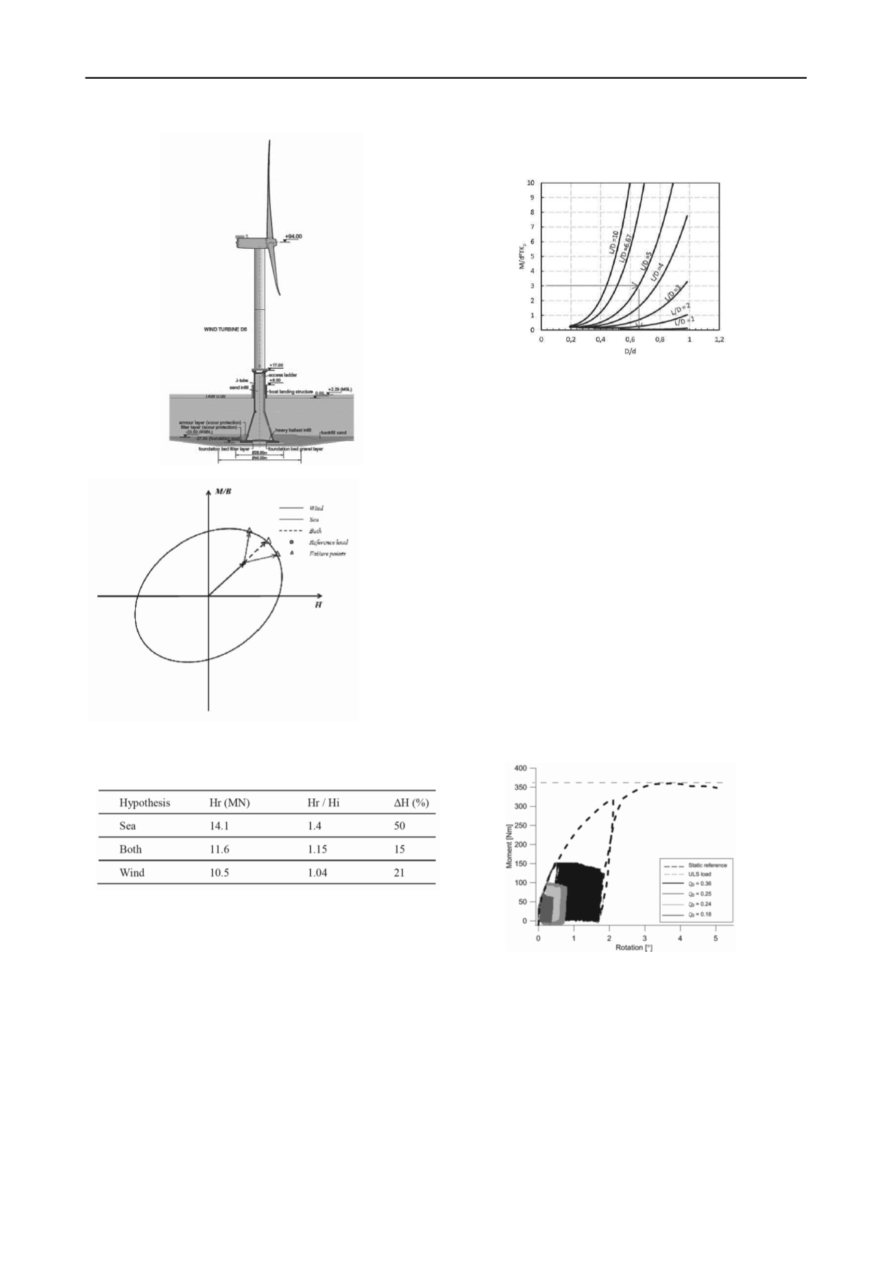
Figure 4. Incremental loading paths to failure.
Table 3. Results of analysis on incremental load to failure.
2.3.2
Hybrid foundations
When considered as a monopile design, the addition of a
shallow footing at seabed level may be thought of as adding
“fixity” to the monopile “head” thereby generating improved
resistance and stiffness to lateral loading, Figure 1. A simplified
design analysis would assess the limiting moment capacity of
the shallow foundation acting alone and include the equal and
opposite moment resistance to the analysis of the monopile.
The shallow foundation not only increases load carrying
capacity but also reduces the bending moment supported by the
monopile, by about 25% in the example cited by Arshi et al
(2013).
Experimental modelling of these hybrid systems at 1g and in
the centrifuge are described together with numerical and
analytical work. The significance of the geometric ratio of
footing to pile diameter, and pile length to pile diameter is
demonstrated and a form for design charts proposed, Figure 5.
Some tests on caisson/monopile combinations are noted and
indicate additional benefit due to the lateral load resistance of
the caisson. Centrifuge tests are currently underway to define
better the benefit of caisson versus simple shallow foundation in
such hybrid foundation systems.
(Arshi et al 2013)
Figure 5. Moment resistance chart for hybrid foundations.
2.3.3
Lateral displacement due to cyclic loading
The focus above is the limit resistance of offshore wind tower
foundations subject to a single application of combined loading.
In practice, the structures are subject to several episodes of
extreme loading caused by major storms and a great number of
cycles of low amplitude loading from normal wind and wave
conditions. The latter source of repeated loading may cause
fatigue or serviceability problems (Roesen et al. 2013).
The authors report a series of 1g laboratory tests on
monopiles in sand subject to one-way cyclic loading over more
than 50,000 cycles.
One limitation in these 1g tests is a more
rigid pile compared with a typical prototype, but the trend of
results should be similar. The cyclic loading is described by
two non-dimensional ratios: the maximum moment compared
with the static moment capacity
ζ
b
= M
max
/M
static
in the range
1 >
ζ
b
> 0; and the ratio of the minimum to the maximum
moment
ζ
c
= M
min
/M
max
which has a value 1 for a static test, 0
for one-way loading (the case examined by Roesen et al) and -1
for two way cyclic loading.
The pile displacement is measured by the rotation θ at the
soil surface. The results of a static load test and the measured
displacement in one-way cyclic load tests (
ζ
c
= 0) with load
intensity
ζ
b
= 0.2 to 0.4 are shown on Figure 6.
(Roesen et al 2013)
Figure 6. Static and cyclic one-way loading tests on model monopiles.
The incremental rotation due to one-way cyclic loading may
be quantified with respect to the rotation caused by the first,
single loading
Δθ
N
= θ
N
– θ
1
. Tests with different loading
intensity may then be compared through the non-dimensional
form
Δθ
N
/θ
1
as shown on Figure 7.
The test data are compared with a simple power law
(
Δθ
N
/ θ
1
) = aN
b
, where
a
and
b
are empirical constants found
from testing. The power law seems to provide a reasonable
asymptotic limit for the data after about 1000 or more load
repetitions, Figure 7. The value of the constant
a
is found to
vary almost linearly with the applied load magnitude
ζ
b
. The
slope of accumulating displacement with repeated loading, the
constant
b
, appears to be a function of the combination of


