2305
Technical Committee 209 /
Comité technique 209
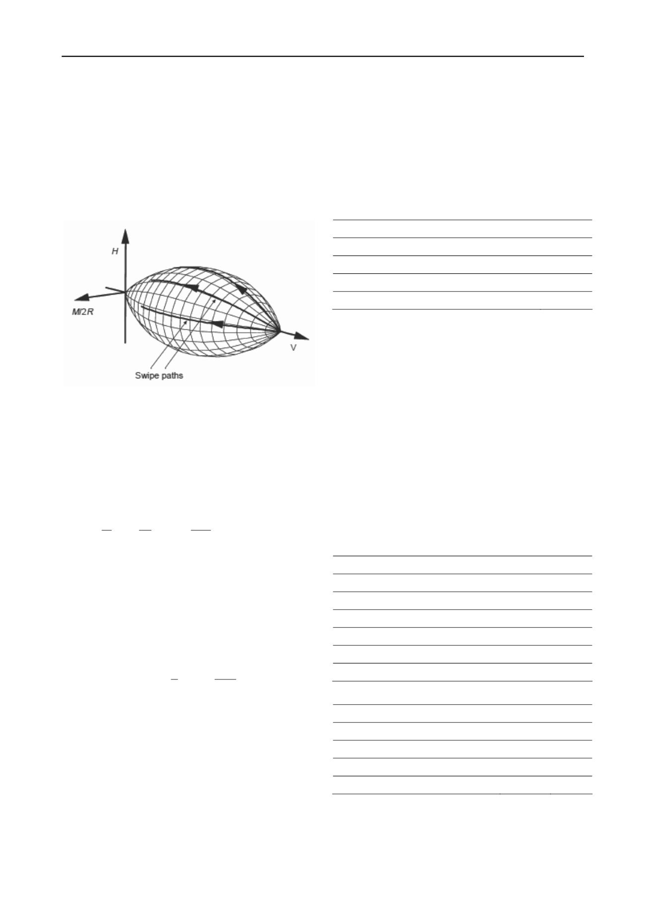
design load are collinear) or sliding (incremental loading
direction collinear with the Horizontal component of the
reference design load). Another particular case included is that
of “plastic overturn”, a prescribed check for breakwater design
in Spanish regulations (Puertos del Estado, 2005) in which the
lever arm of the horizontal loading is maintained (i.e. the
incremental load is aligned with the the Horizontal and Moment
components of the reference load).
3.3
Example formulations
Figure 3 Failure envelope by Gottardi et al (1999)
There are many failure envelopes in the literature. For
foundations failing without drainage at the soil-foundation
interface Gourvenec & Randolph (2011) offer an excellent
review. For the example below a sand profile is assumed and
drained conditions are reasonable. In these circumstances a
convenient expression for a failure envelope is that proposed by
Gottardi et al. (1999) (Figure 3)
2
2
2
0
0
0 0
( , , )
2
(4 (1 )) 0
F V H M
h
m
hm
a
v v
h
m
h m
(3)
Where (a, h
0
, m
0
) are shape factors, empirically determined
as (-0.22, 0.12, 0.09) for quartzitic sand, and we use a non-
dimensional notation in which
v
= V/V
0,
h
= H/V
0,
m
= M/(DV
0
)
and D is the foundation diameter. The normalizing factor V
0
is
the maximum load (i.e. centered vertical) that the foundation
can sustain. Here that maximum load is computed assuming no
embedment and introducing the bearing capacity factor
N
from
Bolton & Lau (1993) into
2
0
1
2
4
D
V DN
(4)
It is worth noting that (a) it is relatively straightforward to
generalize expression (3) to more complex loading situations –
e.g. Lesny 2010- although the experimental base for adjusting
the parameters in those circumstances is somewhat scarce, (b)
that the shape of (3) above has proven rather resilient and very
similar expressions have been found to fit well other foundation
test results in materials like carbonate sand or even clay (Martin
& Houlsby, 2001), as long as the contact surface remains
drained. Of course the choice of V
0
would change according to
the material and foundation shape.
4 EXAMPLE APPLICATION
To illustrate the argument we propose an example, synthetic but
realistic. The case is developed using the characteristics of the
gravity base substructure built at Thornton Bank (Peire et al.
2009) and the design loading specified for a Baltic windfarm
development site, Kriegers Flak (Bulow et al, 2009). This
reference gives some basic characteristics for the OWT
superstructure (Table 1).
Table 1 Super-structure characteristics
Rated power
5 MW
Rotor diameter
126 m
Nacelle height above msl
90 m
Nacelle-rotor weight
4.1 MN
Tower weight
3 MN
The same reference also includes resultants from ambient loads
for a range of depths and load hypothesis (e.g. extreme, fatigue).
Using these data, Table 2 has been computed for a 30 m depth
case and extreme load scenario. It appears that, in this particular
case, 80% of the total horizontal thrust is due to sea action, but
this load is the source of less than 20% of the overturning
moment at foundation level. This might partly reflect the fact
that at that particular site sea current is relatively strong,
lowering the action line of sea forces.
These ambient loads should be combined with the OWT
selfweight. Using the Thornton Bank design like a template for
substructure shape, the relevant characteristics of that part of the
OWT are those listed in Table 3. As usual with gravity base
OWT, the dead weight of the substructure is significantly larger
than that of the superstructure. Combining all environmental
actions and structure selfweight the resultant load combination
acting at the foundation level is (H, V, M) = (10.1; 44.5; 284.3)
in MN and MNm. This will be the reference design load state in
this example.
Tabla 2 Ambient loading parameters
Parameter / load
Unit
Value
Total thrust, H
MN
10.1
Total overturning moment, M
MNm
284.3
Wind thrust, Hw
MN
2.03
Wind arm lever, bw
m
120
Sea thrust, Hs
MN
8.07
Sea arm lever, bs
m
5
Tabla 3 Thornton Bank type substructure characteristics
Parameter / load
Unit
Value
Base diameter
m
23,5
Concrete weight
MN
30
Fill weight
MN
38
Buoyant volume
m3
2965
From that reference state we probe the failure surface
alongside three different incremental loading paths. One will
correspond to a simultaneous and proportional increase of all
ambient actions (the “plastic overturn” case). The other two
hypothesis would correspond to increases of just one of the


