2314
Proceedings of the 18
th
International Conference on Soil Mechanics and Geotechnical Engineering, Paris 2013
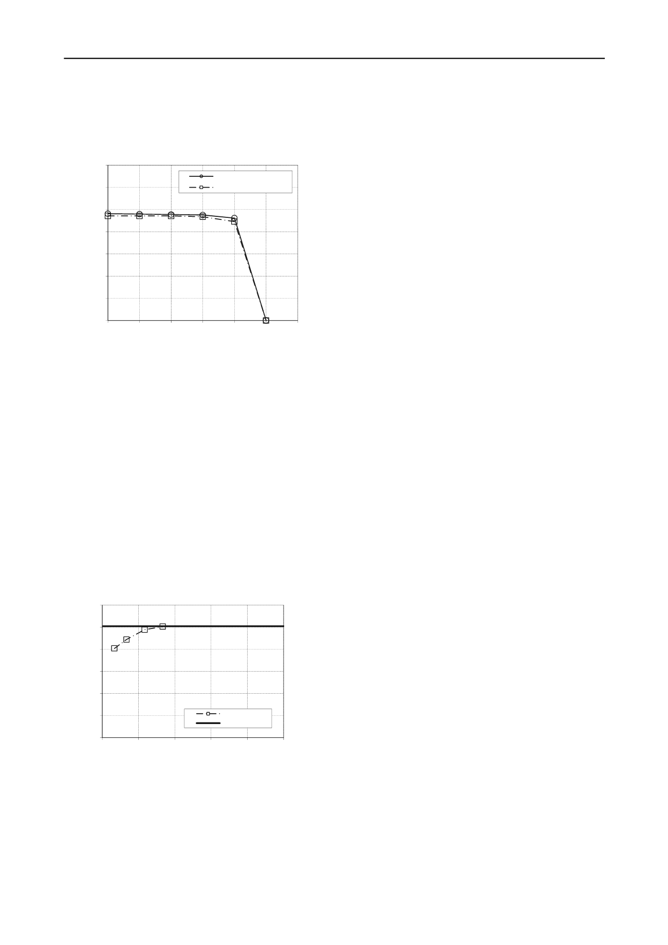
For the second position (at the corner), the normalized
uniaxial vertical capacity is not affected, meaning that the safety
factor for a pure vertical load remains 2.5. The moment capacity
is only reduced by 1 to 3 % (Figure 6) depending on the applied
horizontal load. This is a negligible difference.
0.0
0.2
0.4
0.6
0.8
1.0
1.2
1.4
0
0.1
0.2
0.3
0.4
0.5
0.6
M/S
u0
B³ [-]
H/S
u0
B² [-]
v=0,4 - No pug mark - 3D
v=0,4 - Pug mark - 3D
²
Figure 6. Influence of pug mark on MH failure envelope – Position 2 (at
mudmat corner)
Similarly to the 2D plane strain approach, the inter-distance
between the mudmat and the pug mark was progressively
increased for the position of the pugmark along the width of the
mudmat and the results are presented on Figure 7. The
maximum moment capacity increases progressively with the
inter-distance towards the capacity obtained for the case without
pug mark. From an inter-distance d/B = 0.25, the pug mark has
no effect anymore. This result illustrates the benefit of
considering a more realistic 3D analysis when facing this kind
of problem. The inter-distance required to have no influence of
the pug mark in the 3D model is half the inter-distance required
in the 2D plane strain model.
Finally, Figures 5 and 6 allow the comparison of the effect of
the orientation of the moment and the horizontal loads on the
MH envelope. The moment capacity for the loads in the
direction of the corner is about 5% lower than for the case
where the loads are towards the width of the mudmat. This
geometrical effect is however limited.
0.0
0.2
0.4
0.6
0.8
1.0
1.2
0
0.2
0.4
0.6
0.8
1
M/S
u0
B³ [-]
Inter-distance d/B [-]
V=0.4Vult - 3D
No pugmark
Figure 7. Influence of pugmark / mudmat inter-distance on maximum
moment capacity – 3D analyses
5.3 Conservativeness of 2D Analyses
Simplified 2D plane strain and more realistic 3D simulations
give similar results if the pug mark is not considered.
In the case where the pug mark is located along the width of
the mudmat, the MH failure envelope is degraded in both 2D
and 3D analyses. However, the effect is significantly larger in
the 2D analyses for which the moment capacity is reduced by
55% to 80% depending on the applied horizontal load. In the
more realistic 3D analyses, the moment capacity is only reduced
by 20 to 28%. When the pug mark is located at the corner of the
mudmat, the 3D analyses show very little impact on the mudmat
capacity.
The analyses show also that the distance of influence of the
pug mark on the mudmat stability is 2 times less in 3D
compared to 2D analyses. The maximum moment capacity is
not affected from an inter-distance d/B = 0.25 in 3D analyses
while the distance is d/B = 0.5 in 2D analyses.
1 CONCLUSION
The presence of a pug mark has been found to degrade
significantly the yield surface of a square mudmat in the VHM
load space. However, a comparison between simplified 2D
plane strain and 3D analyses has shown that the beneficial 3D
effects are substantial. If the pug mark is located along the
width of the mudmat, the more realistic 3D model shows that
the moment capacity is only reduced by 20 to 28% depending
on the applied horizontal load. The impact of the pug mark is
significantly larger when a more simplified 2D plane strain
approach is followed. Moreover, in the particular example
treated in this paper, it was observed that a pug mark located at
the corner of the mudmat does not influence its stability. The
zone of influence of the pug mark is also much more limited
when the problem is modeled in 3D and the orientation of a
complex VHM loading scheme can be considered in the global
stability. Simplified 2D plane strain simulations can lead to
over-conservative results for this particular problem.
6 ACKNOWLEDGEMENTS
The authors acknowledge the permission of Fugro
GeoConsulting to publish this work and the guidance and
review provided by Dr Richard Jewell.
7 REFERENCES
Dean E.T.R. 2010.
Offshore geotechnical engineering – Principles and
practice
. Thomas Telford, London.
Gouvernec S., Randolph M.F. and Kingsnorth O. 2006. Undrained
bearing capacity of square and rectangular footings.
Int. J.
Geomech
.
6
, N°3, 147-157.
Hossain M.S., Dong D., Gaudin C. and Kong V.W. 2012.
Skirted
spudcans and perforation drilling for installation of spudcans close
to existing footprints
. Proceedings of the 7
th
Intern.Conf. Offshore
Site Investigation and Geotechnics, London.
Salgado R. 2008.
The Engineering of Foundations
. McGraw-Hill, New-
York.
Plaxis 2011.
Finite element code for soil and rock analyses
, Version
2011. Plaxis BV. Delft, Netherlands.
Limitstate Ltd 2009.
Geotechnical software for stability analysis,
Version 2
. Limitstate Ltd. Sheffield, UK.
Smitts C. and Gilbert M. 2007.
Application of discontinuity layout
optimization to plane plasticity problems
. Proc. of the Royal
Society A.
Martin C.M. 2004.
User guide for ABC – Analysis of bearing capacity
.
Department of Engineering Science, Oxford University, Oxford.


