2312
Proceedings of the 18
th
International Conference on Soil Mechanics and Geotechnical Engineering, Paris 2013
shear strength gradient, B the mudmat width and s
u0
the
undrained shear strength at mudline.
A cylinder of soil with remoulded properties is considered to
model the pug mark. This cylinder extends to the bottom of the
soft layer. A 30 m diameter cylinder corresponds approximately
to a 15 m diameter spudcan. The remoulded zone created by the
penetration and extraction of a spudcan has indeed been
observed to be of the order of 2 times the spudcan diameter
(Hossain, 2012). On removal of the jack-up unit, the spudcans
leave depressions at the site. The depth and configuration of the
depression depends on several factors including soil strength,
spudcan final penetration, amount of soil backfill during
installation, etc. A seabed depression of 2m is considered in this
paper. To keep the model geometry simple, a horizontal
depression with vertical walls is modelled, as illustrated on
Figure 1. A remoulded undrained shear strength profile s
ur
= 2 +
0.4z (in kPa), where z is the depth in meter below original
ground level, is considered within the pug mark area.
Position 1
Position 2
B = 30 m
B = 30 m
D =30 m
V
15 m
Remoulded soil
2 m
Intact soil
d
M
H
Figure 1. Problem geometry: plan view and cross-section
3 FINITE ELEMENT MODEL
2D plane strain and 3D FE simulations were carried out using
Plaxis (Plaxis, 2011). The 2D analyses only consider a pug
mark along the width of the mudmat while the 3D analyses
consider two positions for the pug mark: along the width and at
the corner.
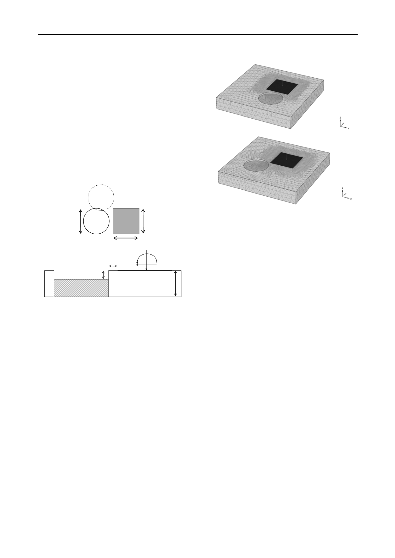
An example of 3D finite element mesh is shown on Figure 2.
Similar mesh discretization was adopted for the different
analyses. The external boundaries were set sufficiently remote
so as not to intercept the different failure mechanisms.
Preliminary analyses were first performed for the base case
without a pug mark and for which analytical and/or numerical
solutions exist. The aim was to check for any effects due to
mesh size on the accuracy of the solution. A compromise was
found between the accuracy of the solution and computational
time. It is estimated that the over-estimation of the true solution
due to discretization errors was maximum 10% for the selected
mesh, which was judged to be reasonable.
Figure 2. 3D Finite Element meshes
The soil is modelled as an isotropic elasto-perfectly plastic
continuum, with failure described by the Mohr-Coulomb yield
criterion. It is assumed to behave “undrained” and is
characterized by a cohesion equal to the undrained shear
strength s
u
with
u
=0. The elastic behaviour was defined by a
Poisson’s ratio
=0.495, and a constant ratio of Young’s
modulus to undrained shear strength E/s
u
=300 for both
undisturbed and remoulded clays.
The strength of the mudmat/clay interface is modelled using
an interface factor
, where the maximum shear stress at the
interface
max
=
s
u
. The “rough” and “smooth extremes of
interface strength correspond to
= 1 and
= 0 respectively.
An intermediate roughness was assumed with
= 0.5, which is
a typical assumption for steel/soft clay interface. A no-tension
condition allowing separation of the mudmat from the seabed
was permitted at the mudmat/clay interface.
The jacket mudmat is modelled as a 30 m by 30 m rigid
plain square plate. The seabed is assumed to be perfectly flat
below the mudmat.
4 DESIGN PROCESS
The vertical load V from the mudmat and jacket structure is
generally known and well-defined. It should typically be limited
to a maximum of 50% the uniaxial vertical capacity. Then, for a
given mobilisation ratio of the uniaxial vertical capacity
v = V/V
ult
, the stability verification consists of ensuring that
there is adequate factor of safety on the ‘live’ loading M and H.
This can be performed by comparing design load combinations
to the MH failure envelope. The higher the mobilisation of the
uniaxial vertical capacity, the lower the moment and horizontal
capacity, i.e. the MH failure envelope shrinks with increasing v.
M and H loads are applied in the direction of the pug mark
centre, namely perpendicular to the side of the mudmat or along
its diagonal.
The presence of a pug mark with remoulded soil conditions
in the vicinity of a mudmat has two adverse effects. First, it
affects the moment and horizontal capacities for a given v.
Second, it reduces V
ult
and therefore increases v, reducing
further the moment and horizontal capacities.


