2317
Technical Committee 209 /
Comité technique 209
extraction.
K
s
is the lateral earth pressure coefficient assumed
conservatively equal to 0.5 by neglecting the effect of
compaction.
Results of static analysis of uplift failure (Table 3) indicate
that, as expected, the second and third approaches are less
conservative in static conditions; however they appear to better
represent the physical reality (i.e. the destabilizing force on a
fully submerged pipe is independent of the depth below the
water table).
In seismic conditions, Italian Building Code (NTC, 2008
§7.11.1) requires that Eq. (1) shall be checked using
1
=
2
=1,
which result in uniqueness of the approach in seismic analysis
(i.e. the difference between
G
d
and
V
d
is the same using a total
stress analysis or an effective stress analysis).
Using a pseudo-static approach the vertical inertial force
F
V
acting on pipes, soil, concrete is assumed upwards and
proportional to relevant weights by the seismic coefficient
k
v
(=0.046) defined in Italian Building Code (NTC, §7.11.3.5.2).
It is well recognized that in the presence of earthquake, a
build-up of pore water pressures can occur with respect to static
conditions. A simplified procedure to account for this
phenomenon is the introduction of the pore-pressure coefficient
r
u
=
u/
’
v0
assumed constant with depth (e.g. Ebeling and
Morrison, 1992; Kramer, 1996). Accordingly, the unit weight of
water and submerged soil are given by:
w sat
u w u w we
r
r
'
(3)
u w sat
u
e
r
r
1
1'
'
(4)
For
r
u
= 1 soil liquefaction occurs which implies that (a)
upward action acting on pipes is proportional to
we
(=
sat
)
instead of
w
. and (b) the submerged weight of the soil block
and soil resistance
R
d
vanish.
In seismic analysis the coefficient
r
u
shall be selected on the
basis on seismic input (magnitude and maximum acceleration),
as well as soil characteristics. In the analyzed case the presence
of a coarse backfill (gravel) around the pipes (Fig.3) is expected
to strongly limit the build-up of pore water pressure. Hence, the
seismic analysis of uplift are performed assuming
r
u
= 0 and
r
u
= 0.1. Results of seismic analysis shown in Table 3 indicate that
also for
r
u
= 0.1 the inequality (2) is satisfied.
2.4 Pipe deflection
Flexible conduits fail by excessive deflection rather than by
rupture of the pipe wall. It is necessary, therefore, to estimate
the deflection of this type of conduit and to establish limits of
allowable deflection for the proposed installation.
Table 3. Uplift analysis
Static conditions
Seismic conditions
Action
(kN/m)
appr.1
appr.2
appr.3
r
u
= 0.1
r
u
= 1
V
d
174.1
86.6
82.3
86.6
159.9
W
pipes
4.0
4.0
-
4.0
4.0
W
soil
87.6
44.4
44.4
40.0
0
W
slab
85.3
49.0
49.0
45.3
11.6
F
v
0
0
0
-8.1
-8.1
G
d
159.2
87.7
84.1
81.2
7.5
R
d
15.6
15.6
15.6
13.4
0
R
d
+G
d
174.8
103.3
99.7
94.6
7.5
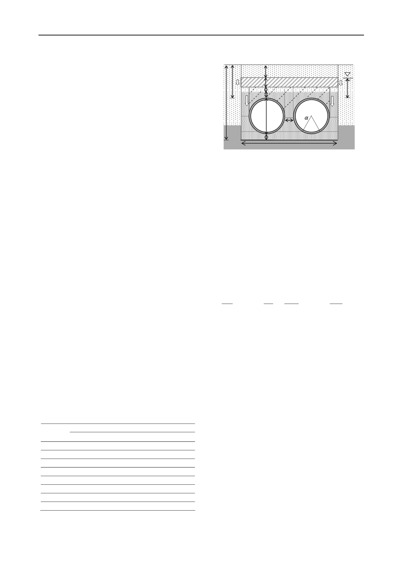
h
3
H
s
B
d
A
’
C
B’
E
D’
F
h
1
D
E’
G G’
clay
GRAVELLY SOIL
H
exc
Concrete slab
Native sand
F’
h
0
h
2
A
B
C’
D
e
H
w
bedding
haunching
Figure 3. Details of pipe installation
For flexible conduits the vertical deflection
y
mainly
depends on the actual load acting on the pipe and the stiffness of
the backfill at the side of the pipes whereas the contribute of
pipe stiffness is generally small (i.e. Rogers et al. 1995). In the
specific case, the presence of two pipes as well as of the
concrete slab makes the analysis more complex than the
classical solutions available in the literature.
2.4.1 Load on pipes
According to Young and Trott (1984), the pair of pipes can
be considered as equivalent to a single pipe of overall width
D’
where
D’
= 2
D
e
+
d
. The load on
D’
is calculated by taking the
lesser of the two values obtained by the complete ditch
condition (
P
1
) and the positive projection condition (
P
2
). This
load is taken as being shared equally by the two pipes.
The load acting on a pipe (stiffer than side fill) in a trench
with a partially submerged homogeneous backfill (see Fig.3) is
given by Bulson (1985):
B
H
B
B
H
B P
w
w
2
exp 1
2
2
exp 1
2
2
2
1
(5)
where
is a coefficient ranging from 0.11 to 0.19 depending
on soil type,
is the total unit weight of backfill. In the analysed
case actual backfill unhomogeneity is accounted for by
assuming a weighted average unit weight (
av
).
For a positive projection conduit the
P
2
value depends on
the relative settlement between the soil prism above the pipe
and the adjacent soil, which determines positive or negative
arching. In the specific case, the presence of the slab prevents
the occurrence of complete ditch or projection conditions.
Moreover, considering that the ratio
H/D’
is very small, it is
reasonable to neglect arching. Therefore, the value of
P
2
is
assumed to be the weight of overlying prism of width
D’
.
Obviously, the maximum deflection is expected to occur at
the section with the maximum cover (3.30 m) with the lowest
groundwater level (-1.60 m below g.l.). With reference to
Figure 3, for
h
1
= 1 m,
s
= 0.30 m,
h
2
=1.7 m,
h
3
= 0.3 m,
H
w
=1.7 m
av
= 20.85 kN/m
3
= 0.19,
P
1
and
P
2
are calculated as
281 kN/m and 264 kN/m, respectively. Following the
suggestion of Young and Trott (1985), the load acting on a
single pipe (
P
) is taken as 132 kN/m.
2.4.2 Backfill
A large part of ability of flexible pipes to support vertical
load must be derived from the passive pressures induced as the
sides move outward against the soil. Therefore, any attempt to
analyse the behaviour of the flexible conduits must take into
account the soil at the sides as an integral part of the structure,
since such a large proportion of the total supporting strength is
attributable to the side material.
Considering that compactive effort is restricted by the
geometry of the trench and the difficult in compacting
underneath the pipe in the haunch zone (Fig.3), as well as the


