2318
Proceedings of the 18
th
International Conference on Soil Mechanics and Geotechnical Engineering, Paris 2013
sensitivity of installed flexible pipe to compaction of material
around it, a clean gravelly soil has been selected as structural
backfill (i.e. the part of backfill that extends from the base of the
bedding to a maximum of 30 cm above the pipe, as shown in
Fig.3). This coarse-grained soil is preferred over native silty
sand for easy of compaction, high earth pressure response and
stability when saturated and confined. The same material – well
compacted - has been used also as bedding soil (Fig.3).
2.4.3 Calculation of pipe deflection
The pipe deflection is predicted by the method of Spangler
(1941) or Iowa formula, although it is well recognized that this
method contains some debatable assumptions.
'E .
REJ
PKD y
L
061 0
3
(6)
where
y
= vertical deflection of pipe (m);
P
= vertical load
on the pipe (MN/m);
EJ
= flexural pipe stiffness (MNm
2
/m);
R
= mean radius of the pipe (m);
D
L
= time-lag factor (-);
K
=
bedding constant (
K
= 0.1 for bedding angle
= 60°, see Fig.3).
E’
= horizontal modulus of soil reaction (MPa).
Considering the absence of vehicular loading and the
prevalent recreational use of the site, live loads have been
neglected. In design the sheet pile extraction is accounted for
using the value of
E’
relevant to a dumped backfill (Table 4). In
long term analysis a time lag factor of 1.5 and a reduced pipe
stiffness are considered (see Table 1). With the above
assumptions short term and long-term deflections are calculated
as 10.1 cm and 20.5 cm , respectively.
Numerous authors have reported that pipes have been
distorted by 10-20% and still continue to perform adequately.
Therefore the theoretical deflections have been considered
acceptable, but a monitoring activity was planned during
installation.
3 COMPARISON OF ACTUAL AND THEORETICAL
DEFLECTIONS
The large diameter of pipelines allowed accessibility and
direct measurement of vertical diameter at prescribed positions
during the various stages of installation (structural backfilling,
slab, final backfilling and sheet piles extraction). The trend of
measured vertical deflection versus time is not monotonic,
showing an initial small deflection, followed by a slight
decrease, a sharp increase and a final stabilisation. The observed
trend can be ascribed to the variation of the acting loads
(backfill height and groundwater level) and the different lateral
support offered by the soil before and after the extraction of
sheet piles. Therefore, for the comparison between actual and
theoretical deflections, only the stabilised values are considered
because they better represent the service conditions of the pipes,
with the groundwater level certainly above the crown of the
pipes.
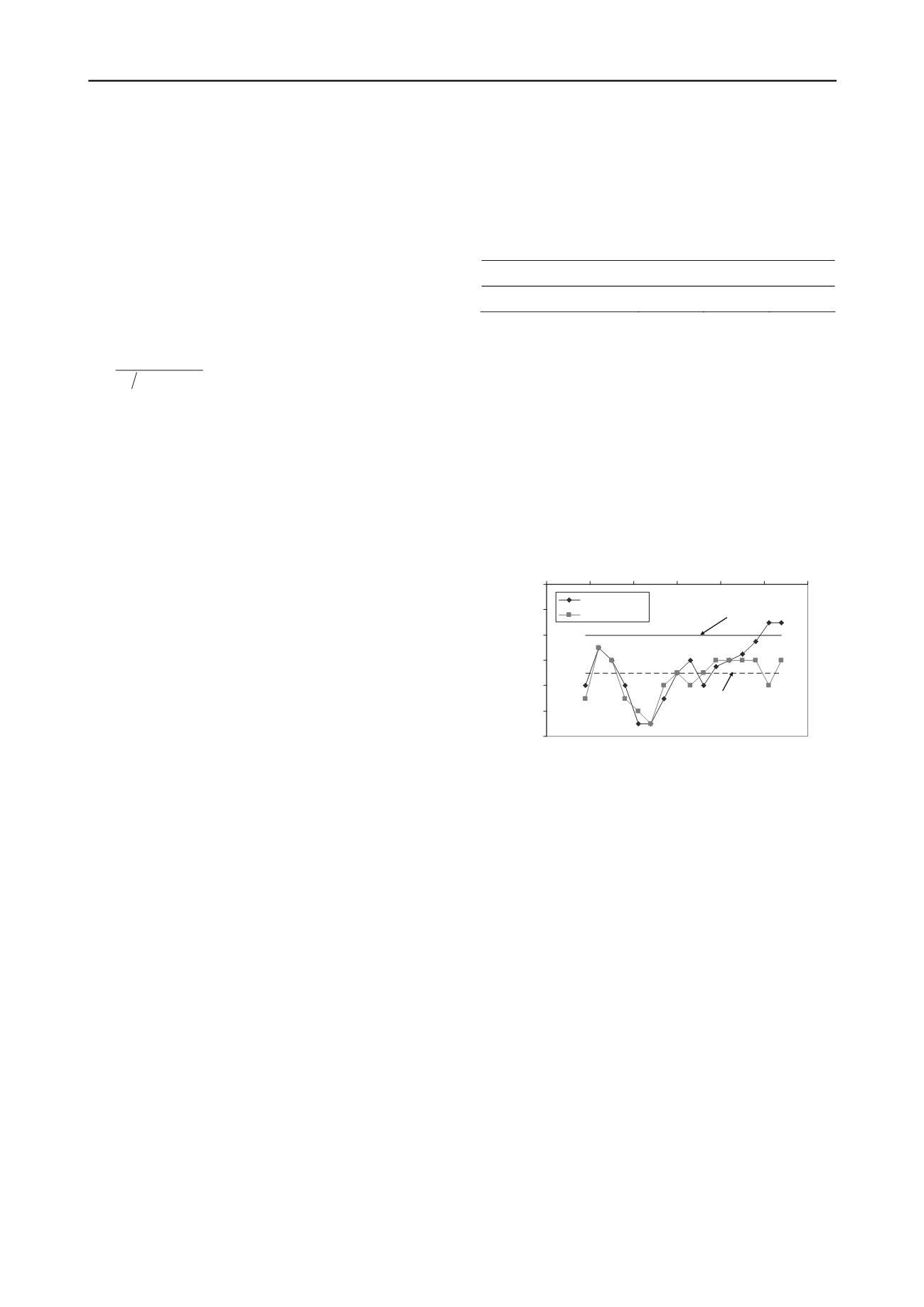
With reference to a pipe stretch 45 m long the vertical
deflections were measured in sections spaced 3 m apart. Final
(stabilized) deflections are shown in Fig. 4. In spite of a quite
uniform cover height the measured deflections vary
considerably along the pipeline with a minimum of 7 cm to a
maximum of 15 cm. This behaviour can be attributed mainly to
inherent differences in compacting the soil beside the pipes and
variable effect of sheet pile extraction. Moreover, variability in
stiffness of native soil can influence the overall response owing
to the closeness of pipes to trench sides.
Considering that measurements refer to a design cover
height ranging from 2.15 m to 2.37 m, the vertical deflection is
calculated by (6) for an average cover height
H
= 2.26 m. The
load on pipe (
P
= 104 kN/m) is calculated following the
suggestion of Young and Trott (1984) discussed previously. The
groundwater level was assumed at 1.6 m below the ground
surface (
H
w
= 0.66 m) based on measurement in the nearby
piezometer. As shown in Fig. 4, the theoretical deflection
calculated by Spangler method is lower than the actual average
deflection. This can be ascribed to effect of sheet pile extraction
which results in a loosening of backfill and a probable increase
of the load on pipes to due to negative arching.
Table 4. Values of
E’
for a clean coarse-grained soil (Howard, 1977)
Degree of compaction
dumped
slight
moderate
E’(MPa)
1.4
6.9
13.8
4 CONCLUSIONS
In the present paper some aspects of design and installation
of two adjacent large diameter pipelines along the Adriatic Sea
coastline in Italy are described.
Uplift analysis is detailed, showing three possible
approaches which lead to different results in static conditions,
whereas in seismic condition a unified approach is proposed
that account for build-up of pore-water pressures.
As far as prediction of vertical deflection is concerned, in
the analyzed case the backfill loosening due to sheet piles
extraction has been modelled by assuming no compaction
(dumped backfill). Despite this assumption, theoretical short
term deflection represents a lower bound of measured
deflections.
4
6
8
10
12
14
16
0
10
20
30
40
50
6
vertical deflection (cm)
0
sea-side pipe
railw ay-side pipe
predicted by (6)
average of measured
deflections
Figure 4. Comparison between measured and predicted short–term
deflections
5 REFERENCES
Bulson P.S. (1985) “
Buried Structures. Static and Dynamic strength
”.
Chapman & Hall ed.. London.
Ebeling, R.M., Morrison, E.E. (1992). “The seismic design of
waterfront retaining structures”.
Technical report ITL-92-11
.
Washington, DC. US Army Corps of Engineers.
EC7 (2004). Eurocode 7: Geotechnical design – Part 1: General Rules.
European Committee for Standardization.
Howard A.K. (1977) “Modulus of soil reaction values for buried
flexible pipeline”. J. of Geotech. Eng. Div. ASCE 103 (1), 33-43.
Kramer, S.L. (1996).
Geotechnical Earthquake Engineering
. Pearson
Education Inc. New Jersey.
NTC (2008). Norme Tecniche per le Costruzioni. D.M. 14/01/2008. (in
Italian).
Rogers C.D., Fleming P.R., Loeppky M.W. and Faragher E. (1995)
“Structural performance of profile-wall drainage pipe – stiffness
requirements contrasted with results of Laboratory and Field
Test”. Transportation Research Record, 1514, 83-92.
Spangler M. G. (1941) The structural design of flexible pipe culverts”.
Bul. 153. Iowa Engineering Experiment Station, Ames, Iowa.
Young O.C., Trott J.J. (1984).
Buried rigid pipes: structural design of
pipelines
. Elsevier Applied Science Publishers. London-New York.
WSSC (2008) Pipeline Design Manual. Part Three - Common Design
Guidelines. Washington Suburban Sanitary Commission.


