2316
Proceedings of the 18
th
International Conference on Soil Mechanics and Geotechnical Engineering, Paris 2013
Table 1. HDPE Pipe properties
Parameter
Weight for unit length (kN/m)
2
External diameter (mm)
2240
Internal diameter (mm)
2000
Moment of Inertia (mm
4
/mm)
45899
Young modulus short term(MPa)
1185
Young modulus long term (MPa)
288
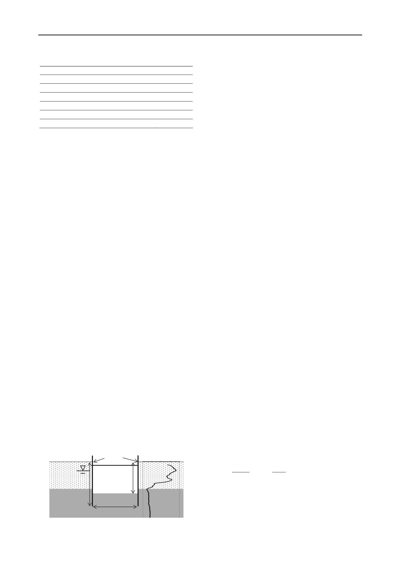
2.2 Underwater excavation
The soil stratigraphy is essentially composed by a sandy layer
3.5-4.0 m thick overlying a cohesive bed. An open standpipe
piezometer installed close to the working area (Fig.1) indicated
that the groundwater table is located 1.0-1.5 m below the
ground level. Fig.2 shows a typical CPT profile with the
characteristic values of geotechnical parameters obtained by
laboratory and in situ tests.
Considering the large pipe diameter, the bedding layer and a
minimum soil cover to counteract buoyancy (as detailed later),
an excavation depth of at least 4.70 m was necessary. Moreover,
a minimum inclination of 0.5% to the horizontal is required to
ensure gravity flow. This results in an excavation depth ranging
form 4.7 m to 6.0 m from ground surface.
Various techniques were considered for the excavation.
Unsupported trench with inclined sidewalls was excluded due to
excessive breadth to ensure stability and the need for continuous
dewatering by well-points. Other equally suitable technologies,
(e.g., soil freezing), were incompatible with the budget.
The selected solution consisted in a 6.1 m wide trench
supported by strutted sheet piles, embedded in the impervious
clay layer. The total length of the sheet piles varied between 8
m and 10 m as depending on excavation depth. Sheet piling
allowed retaining the vertical trench walls, minimizing seepage
into the trench and protecting the working area from tidal and
storm waves (the top of sheet piles was +1 m above g.l., Fig. 2).
To comply with the requirement of minimizing occupation
of the area, the installation of the collectors (270 m) was
realized in four distinct segments (i.e. the excavation in a zone
starts only after the work in the previous zone is completed).
For the first segment, sheet piles were preliminarily installed to
enclose a rectangular excavation zone, creating a continuous
barrier to groundwater along the entire perimeter. For the
subsequent segments, the presence of the installed pipes
prevented to create rectangular hydraulic barrier by sheet piles
only. Therefore, cast-in-place concrete waterproof screens were
designed around the protruding edge of the pipes to block
seepage due to extraction of sheet piles from the adjacent
completed segment.
2.3 Pipe uplift
During the service phase the pipelines are expected to be only
rarely filled by runoff water but permanently submerged by
groundwater and then subjected the buoyancy. Consequently,
the design shall be checked against failure by uplift.
L
=8-10 m
B = 6.10 m
H
exc
>4.7 m
SHEET PILES
STRUT
SILTY CLAY
= 20 kN/m
3
c
u
= 80 kN/m
2
k
=1*10
-8
cm/s
SILTY SAND
= 20.3 kN/m
3
=40°
k
=1*10
-3
cm/s
0
5 10 15 20
q
c
(MPa)
Figure 2. Simplified sketch of the excavation geometry with
geotechnical soil characterization and a typical cone resistance profile.
According to Italian Building Code (NTC, 2008), as well as
Eurocode 7 (2004), for any mass potentially subjected to the
failure mechanism, the following inequality must be satisfied:
d d d
RGV
(1)
where
V
d
is the design destabilizing action acting upwards
(obtained by a partial factor
1
= 1.1 in static conditions),
G
d
is
the design stabilizing permanent action including the weight of
the mass subjected to uplift (obtained by a partial factor
2
= 0.9
in static conditions) and
R
d
is the design soil resistance by
friction along the vertical contours of the assumed block.
Considering the closeness of pipes to the sea (Fig. 1) it can
not be excluded that in the future a portion of the soil above the
pipe can be eroded. To confer protection against erosion a cast-
in-place concrete slab (6.05 m wide and variable thickness) is
realized above the pipes, as illustrated in Figure 3. This solution
allows also to increase the average unit weight of the material
above the pipes and enlarge the size of the block subjected to
uplift. Finally, it represents a protection against accidental
damage due to anthropic activities and the superficial sand layer
enables to continue the recreational use of the beach.
In the application of Eq. (1) different approaches can be
adopted to calculate the term
V
d
and in
G
d
. Eurocode 7 indicates
a total stress analysis for uplift problems (EC7, 2004 §10.2).
According to this approach,
V
d
is the upward resultant of pore
water pressure acting on the
lower
boundary of the assumed
block. Consistently,
G
d
includes the
total
weight of the soil
block above the pipes. However, following this approach, the
resultant of pore water pressure acting downwards is multiplied
by a partial safety factor (
1
=
1.1) different to that applied to the
vertical upward resultant
2
= 0.9). This results in a violation
of the “single source principle” enunciated by Eurocode 7 (EC7,
§2.4.2). According to this principle, when destabilising and
stabilising permanent actions come from a single source, “a
single partial factor may be applied to the sum of these actions
or to the sum of their effects”. Based on the above
considerations, in the second approach the destabilizing action
is assumed to be the buoyancy force on the two submerged
pipes (i.e. the weight of the water displaced by the pipes
W
w
).
Consistently,
G
d
includes the submerged weight of the block
above the pipes. Finally, a third approach can be used in which
the destabilizing action is assumed to be the
resultant
buoyant
force of the submerged pipes, i.e. the algebraic sum of weight of
displaced water
W
w
and weight of pipes
W
p
(WSSC, 2008). This
latter approach implies that the check against failure by uplift is
automatically verified when
W
w
<
W
p
.
The three approaches described previously are applied
assuming the simplified sliding surface shown in Fig. 3, which
implies a failure mechanism involving pipes, slab and soil
above and between the pipes as well (hatched zone in Fig.3).
The results were obtained for the worst-case scenario of
complete erosion of the superficial sand layer (
h
3
= 0 in Fig 3)
and minimum cover thickness above the pipes (
h
1
+
h
2
= 0.5 m,
s
= 0.6 m). The unit weight of concrete and saturated soil were
23.5 kN/m
3
and 20.3 kN/m
3
respectively.
The
R
d
term was calculated as the sum of the friction forces
along the vertical planes on each side of the assumed block (BC,
B’C’, DE, D’E’)
2 2
2 1
3
2
3
)
(
tan '
tan '
s R h hs
K s
K R
e
k
s
BC
s
d
(2)
where
BC
is the interface friction angle between concrete and
the sandy soil (
BC
= 30°),
is the shear resistance angle of the
granular backfill,
3
= 1.25 is the partial safety factor applied to
the shear strength parameters. The angle
k
after backfilling is
assumed to be 40°- 42°, but a reduced value of 38° is assumed
in eq. (2) owing to potential loosening induced by sheet pile


