2304
Proceedings of the 18
th
International Conference on Soil Mechanics and Geotechnical Engineering, Paris 2013
structure (Van der Temple and Molenaar, 2002) or displacement
limits imposed by operating constraints (e.g. foundation tilting
limits of 0.25° - 0.5° are sometimes quoted). However, even if
we narrow our focus to bearing capacity considerations there
are reasonable grounds to question the suitability of the
conventional design approach.
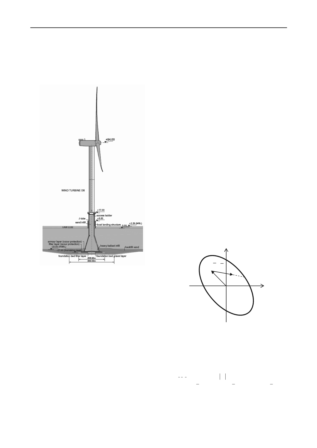
Figure 1. Thornton Bank GBS (Peire et al, 2009).
Indeed there are several aspects of the traditional approach to
bearing capacity that are poorly suited to deal with OWT.
Firstly, using separate corrections for shape, depth, load
inclination, load eccentricity is cumbersome and prone to
calibration error if the effects that are being corrected for are not
truly independent. This is perhaps the reason behind the large
scatter between inclination factor formulations (Siefert & Bay-
Gress; 2000); that uncertainty is particularly undesirable for
structures, like OWT, that are mostly designed to sustain
horizontal loads.
Secondly, the traditional approach to bearing capacity
quickly leads to conundrums when the security format (as is the
case for most modern codes, like DNV-OS-J101) is based on
separate partial factors for loads and resistances. As discussed in
detail by Lesny (2007) the same action might have a detrimental
or favourable effect depending on which other actions are being
simultaneously considered. Also it is fairly evident that a
traditional bearing capacity check is far from eliminating the
most likely path towards failure.
Finally, it is very difficult to generalize the traditional
approach to cases when two major horizontal loads (wind,
wave) are acting in separate planes. All these problems are best
dealt with if the traditional approach to capacity checks is
replaced by a failure-envelope based one.
3 FAILURE ENVELOPES
3.1
Concept
Failure envelopes were introduced (Butterfield & Ticof, 1979)
as an alternative to classical bearing capacity analyses. They
were based on the concept of interaction diagram, which was
applied to the system of loads acting on the foundation. Most
developments to date –but not all-, refer to the case in which
that system can be reduced to loads acting within a plane (V, H,
M
) –where
M
represents the moment acting within the plane, M
normalised by a characteristic foundation dimension, M/B.
Failure envelopes are implicit in the traditional approach to
bearing capacity. However, it was clearly appreciated from the
beginning that an explicit failure envelope was useful to link
previously separate checks on different foundation failure
modes (e.g. sliding and bearing capacity) into a coherent view.
Failure envelopes offered advantages also from the
experimental viewpoint, because they provide a clearer
framework for experimentation, even suggesting new, more
efficient, procedures (like “swipe” tests).
Failure envelopes are also attractive because they can fit well
with generalized force-displacement foundation models
(“macroelements”; Nova and Montrasio, 1991) that are used to
compute foundation displacements and represent an economical
solution to non-linear soil-structure interaction studies. Finally,
failure envelopes are interesting because they enable a more
coherent approach to foundation safety.
3.2
Safety considerations
Already Georgiadis (1985) clearly identified as one major
advantage of failure envelopes that they allow a very natural
consideration of the influence of different loading paths. To do
that, it is important to distinguish between the reference design
load state and incremental loading paths (Figure 2).
M
H
(
H, M
)
(
H, M
)
(
H
r
, M
r
)
Figure 2. Schematic load envelope illustrating a reference design load
and one incremental load path
Any load system (V, H,
M
) shall remain within the failure
envelope. It is however convenient to establish a non-
dimensional safety measure. To do so a simple approach is, for
any incremental loading direction, to obtain the crossing point
with the failure envelope (V
r
, H
r
,
M
r
) and then define a
generalized safety factor, SF, as
V,H,
V,H,
1
r
M
SF
M
(1)
(
,
,
)
r
r
r
r
r
r
V V V H H H M M M
(2)
It is thus made explicit the fact that safety is not only
dependent on the initial design situation but also on the
incremental loading path. This definition includes, as a
particular case, the traditional safety factors against bearing
capacity (the incremental load direction and the reference


