2274
Proceedings of the 18
th
International Conference on Soil Mechanics and Geotechnical Engineering, Paris 2013
flexible mechanism, so that the device moves together with the
ground displacement. A sensor unit covered by a small
aluminum cylindrical case is installed in each segment. The
sensor unit contains the MEMS tilt meter and a geomagnetic
sensor (digital compass, nominal resolution = 0.5 deg) to detect
the direction of unit. Each unit also contains a microcontroller
chip, which control the sensors, and transfer the control
commands and the obtained data to the next units by serial
interfaces. A significant advantage of this device is that it can be
installed quickly into the slope ground being blown with a
hammer, as its diameter is as small as 25 mm. Besides, it can be
installed into a deeper layer of slopes (3-5 m) by connecting the
segments as many as needed.
Unlike conventional sensing devices, such as borehole
inclinometer and extensometer which measures displacements
of slope, measurement with tilt sensors is simple and easy.
However, the translation of the obtained data of tilting angle is
still under consideration. It is because there are few case
histories of early warning with tilt sensors compared to those
with conventional sensors. Therefore, it is essential to observe
the behaviors of tilt angles in prefailure stages of slopes.
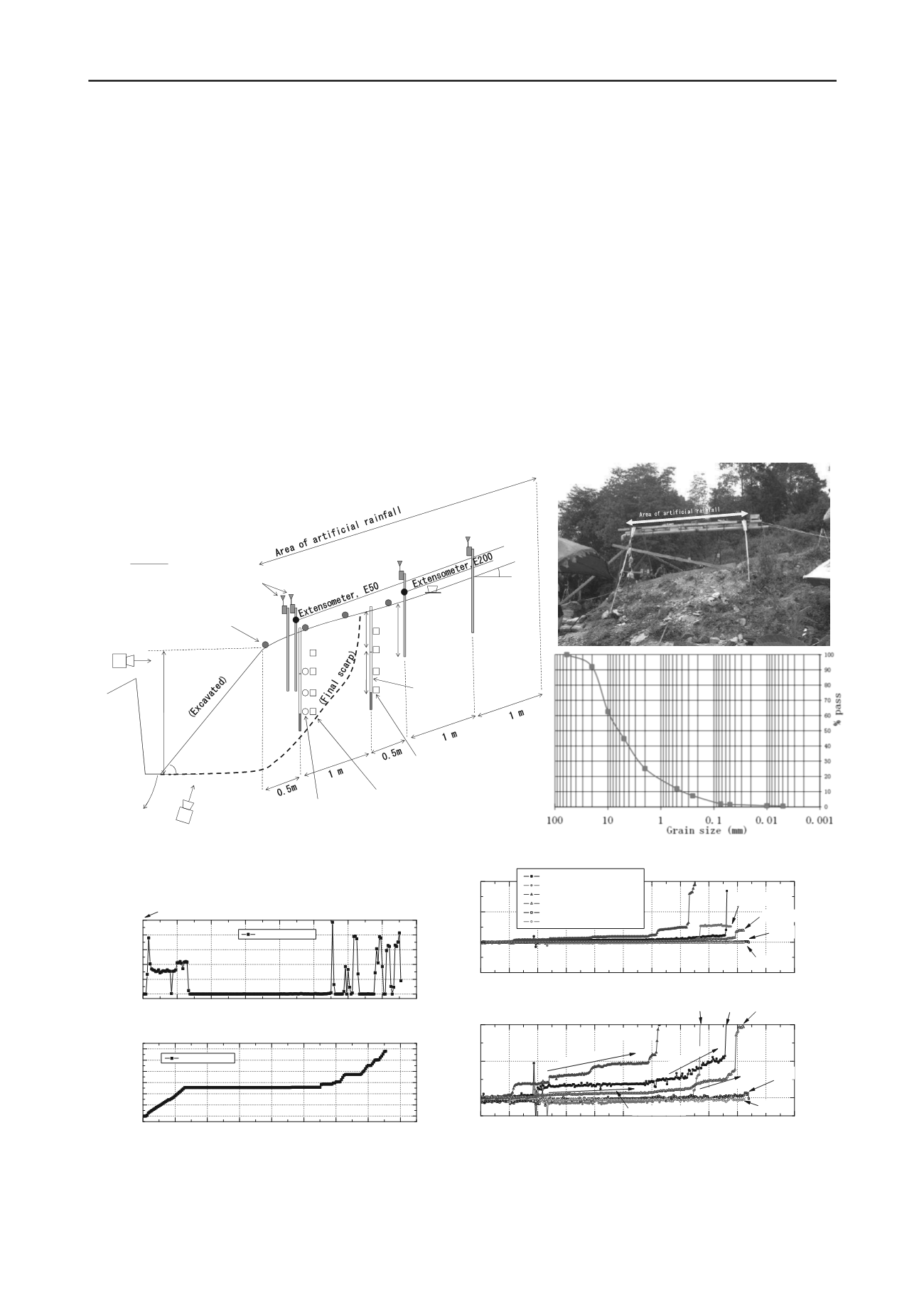
2 SLOPE FAILURE TESTS BY ARTIFICIAL RAINFALL
An artificial rainfall test was conducted on a natural slope of
weathered and loose (N
d
<10 for 10 cm of penetration by
portable dynamic cone penetration tests) andesite deposit in
order to observe its prefailure behaviour. The site is located on
an unstable slope in Taziping, Sichuan Province, China. Figure
2 shows the cross-section and photo of the site together with the
instruments. The slope angle is around 18 degrees, and its lower
end was excavated for a depth of 1.4 m with an angle of 40
degrees. The deposit contains some big rocks with diameter of
300 mm or more. The particle size distribution of component
finer than 100 mm is show in Figure 2. It is a sandy material
containing some gravel and fine particles.
Figure 2 also shows surface tilt sensors (T50-1, T50-2, T200,
and T300), and miniature ground inclinometer (K50 and K150).
The number in the notation of each sensor represents the
distance from the bottom end of slope in cm. Each rod of the
surface tilt sensors was inserted into the ground by 75 cm. Each
miniature ground inclinometer consists of 2 segments with a
length of 500 mm.
Side view:
Deposi t
removed
1. 4 m
Mi ni ature
i ncl i nometer
( 0. 5mx 2uni ts)
Ti l t sensors
T50-1&2
Ti l t sensor
T200
Vi deo
camera
Vi deo
markers
18°
Ti l t sensor
T300
40°
Vi deo
camera
0. 75 m
0. 5 m
0. 5 m
Pore water pressure
sensors, U50
( Depth = 0. 5, 0. 75, 1m)
Vol umetri c water
content sensors, W150
( Depth = 0. 25, 0. 5, 0. 75, 1m)
Rai n
gage
Vol umetri c water
content sensors, W50
( Depth = 0. 25, 0. 5, 0. 75, 1m)
Figure 2. Cross-section, photo, and particle size distribution (finer part than 100 mm) of the site for the artificial rainfall test.
0
4
8
12
16
20
24
28
32
0
10
20
30
40
50
Elapsed time (hour)
Rainfall (mm/ 10min)
Rainfall (mm/ 10min)
2011/ 6/ 29- 11:00
0
4
8
12
16
20
24
28
32
0
200
400
600
800
1000
1200
Elapsed time (hour)
Total rainfall (mm)
Total rainfall (mm)
32 33 34 35 36 37 38 39 40 41 42 43
- 5
0
5
10
K50- upper
Elapsed time (hour)
Tilting angle (deg)
Tilt sensor T50- 1
Tilt sensor T50- 2
Mini- inclinometer K50- upper
Mini- inclinometer K150- upper
Tilt sensor T200
Tilt sensor T300
2011/ 6/ 30- 08:00
T200
T50- 1
T300
T50- 2
K150- upper
32 33 34 35 36 37 38 39 40 41 42 43
0
1
2
0.24 deg/ hour
0.02 deg/ hour
0.4 deg/ hour
0.15 deg/ hour
T50- 2
Elapsed time (hour)
Tilting angle (deg)
2011/ 6/ 30- 08:00
K50- upper
T50- 1 K150- upper
T300
T200
Figure 3. Records of the artificial rainfall. Figure 4. Tilting angles on the slope.


