958
Proceedings of the 18
th
International Conference on Soil Mechanics and Geotechnical Engineering, Paris 2013
reduced further. There is no longer a reliance solely on the
water flow to install the pile. Instead the pile is jacked and the
water injection is used to reduce the required installation loads.
Flow rates for this method reduce to less than 300 litres per
minute, and depend on the size and type of pile being installed.
The aim of water injection is to aid pile installation with
minimal impact to the surrounding ground. Water injection
should only be required during periods of high pile installation
loads. During these phases, high water injection rates would be
required to reduce the installation loads. Once the installation
loads are sufficiently reduced, the flow rate can be reduced
unless pile loads begin to increase again.
Despite the variety of full scale testing completed, there is
still uncertainty over the water injection technique. The main
unknown is the governing mechanism. Some options have been
suggested, most recently the scour system outlined by Schneider
et al. (2008), however further research is required to investigate
the technique further.
3 CENTRIFUGE MODELLING
Initially, the aim of the centrifuge testing was to find an effect
on the pile installation load when using the water injection
system.
3.1 Model construction
A body of fine sand was prepared to a relative density of 80 %
in a centrifuge container, 850 mm in diameter, to a depth of 320
mm. This was saturated from the base with de-aired water.
The sand was prepared so that it possessed a low
permeability by mixing fine Fraction E silica sand with a
commercially available builders sand. To ensure continuity
between tests, the sand was repeatedly sampled and the particle
size distribution (PSD) was found for different batches using the
Single Particle Optical Sizing (SPOS) technique. Figure 1
shows the particle size distribution of the mixed sand compared
with the Fraction E and builders sand components.
Figure 1. PSD comparison of the mixed sand for testing with standard
sand types, Fraction E and a builders sand.
3.2 Model pile
A bespoke instrumented model pile was constructed for the
testing program. A stainless steel tube of 12 mm outside
diameter was used, with a water delivery pipe running through
the centre. Stainless steel was chosen due to its strength,
hardness and resistance to corrosion – preventing buckling
during testing or surface abrasion over multiple installations.
This ensured consistency over all the installations. A
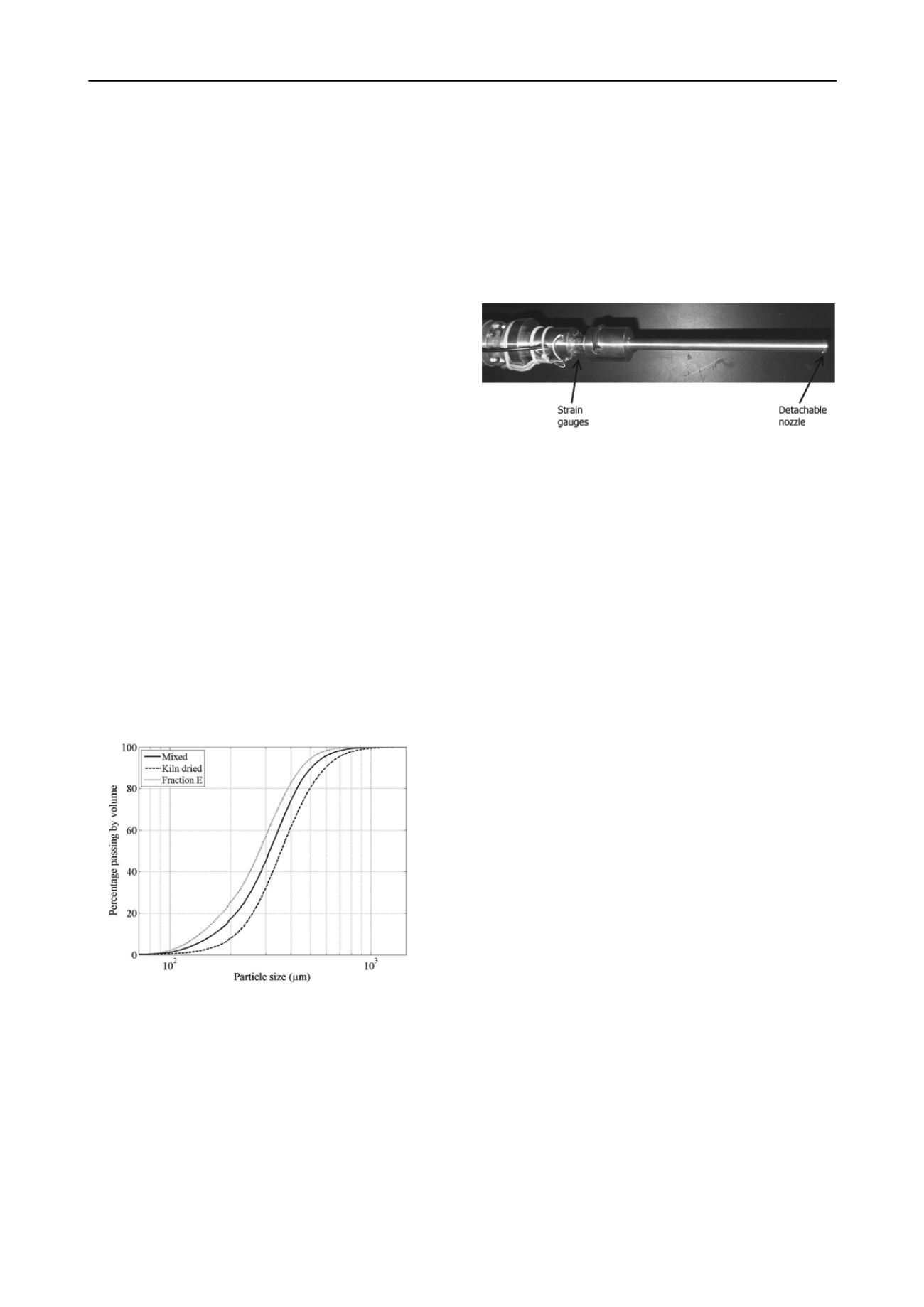
photograph of the pile is shown in Figure 2.
Strain gauges were used to monitor the axial load at the pile
toe and the pile head. Two full Wheatstone bridges were used
at each location.
The water delivery pipe was a 2.5 mm internal diameter
plastic pipe. This terminated at a detachable nozzle at the pile
toe which could be easily changed between tests. Different
nozzles were used throughout the test program. Nozzles using
only a central orifice will be assessed in this paper. These were
modelled on small orifice plates, with a nozzle diameter of 0.5,
1.0, 2.5 and 3.0 mm.
Figure 2. Photograph of the model pile as used, with nozzle attached at
the toe and visible strain gauges at the pile head.
3.3 Water injection system
In order to model the water injection technique, a new system
was required to provide high pressure water to the pile at a
relatively high flow rate. Previous centrifuge testing of water
jetting used low flow rates and pressures, due to the chosen
pumping system.
Typical pumping systems for use one board a centrifuge
package are based on a syringe pump. Such systems are
commonly used for modelling excavations, where fluid is
drained from a region to simulate ground volume loss, or for
simulating pile jetting, such as the jetted spudcan experiments
of Gaudin et al. (2011). Syringe pumps are limited by the
actuator used to drive the piston. The actuator provides a high
degree of control over the flow, but also restricts its use to low
flow rate and low pressures. In addition, syringe pumps
typically have a small volume capacity, meaning it is difficult to
maintain high flow rates for a long period of time.
To avoid this issue during testing, the new system developed
derived water pressure from the radial acceleration down the
centrifuge arm. Water was provided to the slip rings at typical
mains pressure (around 200 kPa) and then fed to the package
through a pipe running down the beam. Moving through the
gravitational field gives an increase in pressure according to:
2
2 2
5.0
ring
slip
package
rings
slip
package
r
r
P
P
(1)
where P is the pressure at the package and slip rings
measured in Pascal, ω is the angular velocity of the centrifuge in
rad/s and r is the radius from the centre of the beam of the
package and slip rings in metres.
This procedure developed peak pressures at the model of 1.2
MPa and sustainable flow rates of up to 3.5 litres per minute.
Water pressure and flow rate were monitored at the centrifuge
model, a short distance from the pile toe. This location was
chosen for the simplicity of mounting a pressure transducer and
a turbine flow meter in the water delivery system. In addition, a
solenoid valve was used to allow or terminate flow to the pile.
Pressure at the pile toe could be calculated following the
centrifuge test using pipe flow theory as laid out by Goforth et
al. (1991). Loss factors can be confirmed by comparing
calculated values with data taken during a flow test – where the
pile toe is suspended above the sand surface and water is passed
through the system. The calculations can then be extended to
allow for different toe positions in the acceleration field and the
toe pressure at all pile depths can be found.
Flow rate control was achieved using a manually operated
flow tap before the slip rings. This controlled the water flow


