962
Proceedings of the 18
th
International Conference on Soil Mechanics and Geotechnical Engineering, Paris 2013
on the shear plane at any time t +Δt is equal to P
n
(t) + k
n
Δ δv
(t+ Δ t), where k
n
is the stiffness of the surrounding rock mass
and Δ δv (t+ Δ t) is the dilation restricted in the given interval of
time. Therefore, shearing of rough joints under such
circumstances no longer takes place under constant normal load
(CNL), but rather under variable normal load where stiffness of
the surrounding rock mass plays an important role in the shear
behaviour. This particular mode of shearing is called as shearing
under constant normal stiffness (CNS) boundary conditions. For
analysis and design of tunnels, foundations and rock slopes,
shear tests results under CNL condition are not appropriate. A
more representative behaviour of joints would be achieved if the
shear tests were carried out under boundary conditions of
constant normal stiffness (CNS).
In past decades numerous shear models have been proposed
based on experimental, analytical and numerical study to find
out the shear behaviour of rock joint. These models available in
the literature fail to appropriately determine shear behavior of
rock due to limitations of boundary condition i.e. CNL
boundary condition is used for modeling like (Patton 1966,
Barton 1973 and 1976, Haberfield and Johnston 1994 and Yang
and Chiang 2000).
But very few studies are available under CNS condition i.e.
constant normal stiffness conditions. To study the shear
behaviour under CNS conditions, the conventional direct shear
test apparatus working under CNL boundary condition is
modified by different researchers like, (Obert et al. 1976, Ooi
and Carter 1987, Johnston et al. 1987, Indraratna 1998, Gu et al.
2003 and Kim et al. 2006) to be used for CNS boundary
conditions.
Despite frequent natural occurrence of infill material, filled
discontinuities have been studied much less, perhaps because of
the difficulties arising from sampling, testing or due to
increased number of variable parameters for constitutive and
numerical modelling. Due to limited research, it is a common
practice to assume the shear strength of an infilled joint equal to
the infill material alone, regardless of its thickness. Kanji 1974
reported that the shear strength of the infilled joint is lower than
that of the infill material. Hence this assumption will lead to
unsafe designs. These uncertainties in estimation have
motivated the present work.
2 PHYSICAL MODELLING OF ROCK JOINTS
It is difficult to interpret the results of direct shear test on
natural rock because of difficulty in repeatability of the sample.
To overcome this problem a model material is searched which
can easily be handled and reproducibility of the sample can be
ensured. To achieve this different brands of plaster of Paris and
dental plasters at different moisture content and curing period in
isolation or combinations have been tried. Finally, plaster of
Paris is selected because of its universal availability and its
mould ability into any shape when mixed with water to produce
the desired joints and also long term strength is independent of
time once the chemical hydration is completed. To characterize
model material a series of physical and mechanical tests on a
number of specimens prepared by mixing the prescribed
quantity of water with plaster of Paris powder were carried
out.
The prescribed percentage of water is decided so as to achieve
proper workability of the paste and required strength to simulate
the soft rock. Different water cement (POP) ratios were tried in
order to obtain desired strength and workability. The ratio
which is finally selected is 0.60.
The physical and engineering properties of the model
material were determined in the laboratory as per the suggested
methods of ISRM 1977 and 1979. The average uniaxial
compressive strength and tangent modulus at 50% of peak axial
stress of model material at 0.60 water cement (POP) ratio and
after 14 days of air curing is 11.75 MPa and 2281 MPa
respectively. Thus, the material can be classified as ‘EL’ based
on Deere and Miller 1966 classification chart, indicating that the
material has very low strength (E) and low modulus ratio (L).
The cured plaster of Paris samples showed a consistent uniaxial
compressive strength (σ
c
) in the range of 10.58 to 13.22 MPa
and a Young’s modulus of 1856 to 2631 MPa. These ranges of
strength and modulus values are suitable for physically and
mechanically simulating the behaviour of jointed rocks like
siltstone, sandstone, friable limestone, clay shale and mudstone.
2.1
Preparation of unfilled rock joint samples
The asperity plate of 15
0
-15
0
angle designed and fabricated by
Rao and Shrivastava 2009 has been used to produce desired
asperity in the sample as shown in Fig. 1(a). The plaster of Paris
with 60% of the moisture is mixed in the mixing tank for 2
minutes and then the material is poured in the casting mould
which is placed on the vibrating table. Vibrations are given to
the sample for a period of 1 minute and then the sample is
removed from the mould after 45 minutes and kept for air
curing for 14 days before testing.
2.2
Preparation of infilled rock joint samples
The infill material is selected to simulate the field conditions. In
the present work combination of fine sand and mica dust both
passing through 425micron sieve and plaster of Paris is selected.
The selected composition is plaster of Paris 40%, fine sand 50%
and mica dust 10% mixed together with water 45% by weight of
total mass of the material. The uniaxial compressive strength of
the 7 days air cured infill material is 3.47 MPa and direct shear
tests carried on the infill material gave friction angle and
cohesion, 28.8
0
and 0 respectively.
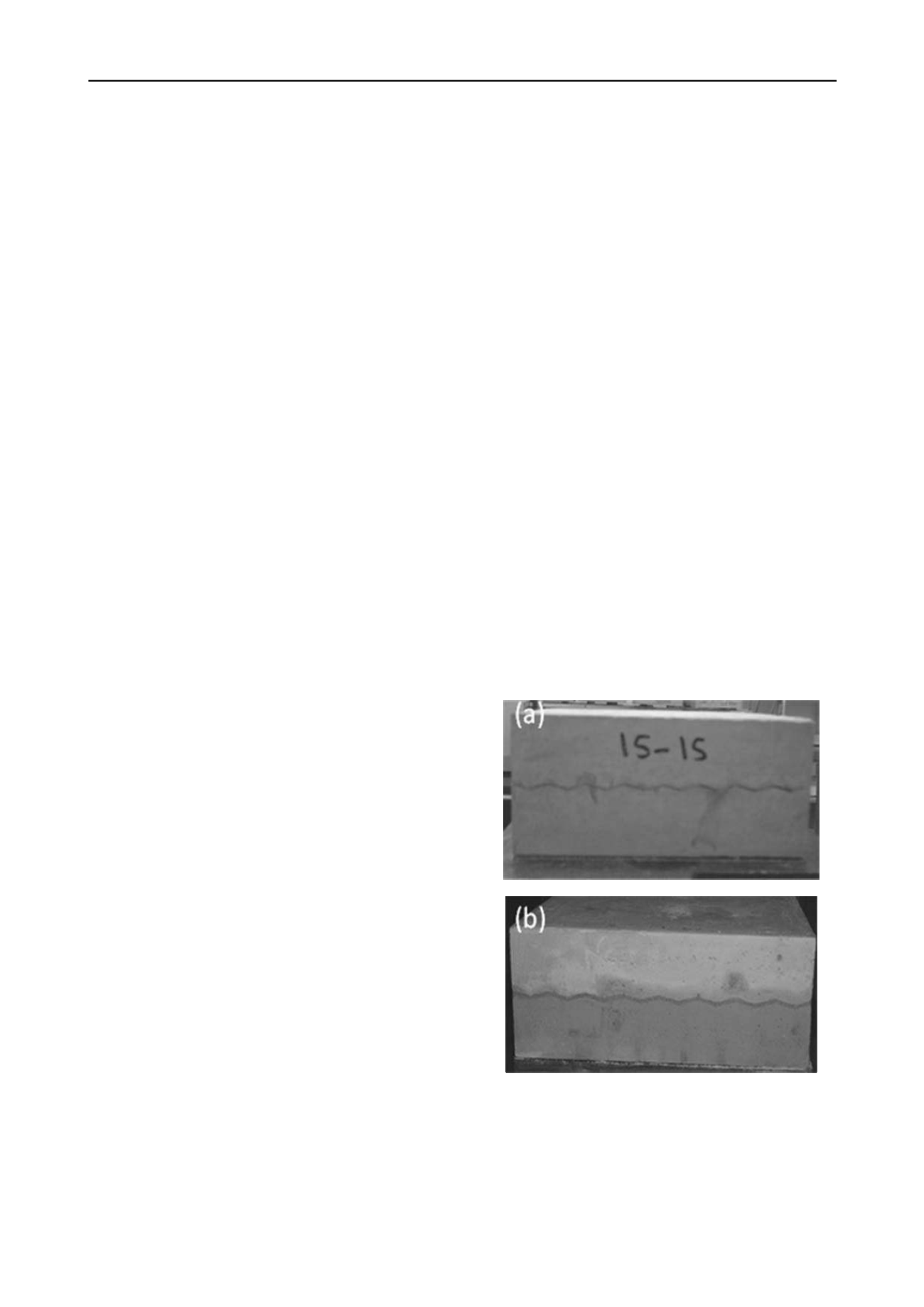
The infill joint with required thickness as shown in Fig. 1
(b) is created on the sample with the help of infill mould
developed by Shrivastava et al. 2011.
Figure 1. Photograph of simulated rock joints (a) unfilled (b) infilled.
The samples are placed on the mould and tighten at suitable
point so that the required thickness of the infill material is
created. The infill material is spread over the lower sample and
the asperity plate is put over the infill material and the asperity
plate is compressed from the top with the help of C- clamps so
that the uniform pressure is applied on the sample and the same


