970
Proceedings of the 18
th
International Conference on Soil Mechanics and Geotechnical Engineering, Paris 2013
rammed in a controlled manner to have a relative density of
80% throughout the column length. In each test, two granular
columns were instrumented for subsurface settlements, the
central column and one of the closest columns to the centre.
Drilling of instrumented columns was done throughout the
foundation soil (290 mm).
A miniature magnetic switch apparatus has been developed
based on the measurement principle of magnetic extensometer
to get subsurface displacements (Tekin 2005). The apparatus
consists of an antenna rod with a base, ring type magnets,
magnetic switch probe and a worm gear device designed to
move the probe inside the antenna rod slowly. After drilling,
long antenna rod (d=6 mm) was inserted into this hole and its
base was placed at the bottom of the tank. The gap between the
bored hole and outer surface of antenna rod was filled with sand
or clay till the desired level of settlement measurement. Then
ring type magnet (d=13 mm) was passed through the rod. At
least eight magnets were placed along 290 mm depth. A hollow
ramming device was used to compact sand at the same relative
density of other columns and for compression of clay.
When all columns were prepared, the surface was flattened;
loading plate and loading frame were mounted. Two
displacement transducers were located on the loading plate to
record plate settlement (total footing settlement). Initial
(reference) magnet locations were determined by moving the
probe slowly inside antenna rods.
Footing load of 75 kPa was applied on clay soil improved
by granular columns. At the end of consolidation (test), final
readings were taken throughout the antenna rods.
In the test series with 200 mm plate, at the end of 75 kPa
loading, test was repeated for 100 kPa loading with settlement
measurements. Figure 1 shows experimental set-up.
Tests without granular column installation (untreated soils)
but with the same loading levels and instrumentation were done
for each loading plate diameter. These reference tests were the
basis of comparisons to find out the contribution of granular
columns to settlement reduction for different column lengths.
Figure 1. Experiment Set-Up
3 TEST RESULTS
Scope of this research involved not only the efficiency of
floating granular column length but also effect of column
number (area replacement ratio) and comparison of end-bearing
columns for footings (B=100 mm, B=200 mm) and 1-D unit cell
(B=410 mm) concepts on settlement improvement. Column
length, loading plate diameter, area replacement ratio and
loading levels were the variables, but clay thickness
(H=290mm) and column diameter (20 mm) were kept constant
in all tests. However, this paper includes only the behavior of
floating granular columns loaded under B=100 mm and B=200
mm plates, therefore only related test series and their findings
were given in this paper. The details of the test series selected
are summarized in Table 4. Area replacement ratio is 0.22 in all
tests. End bearing series in Series III are also included.
Table 4. Summary of test results
Series
No
Loading
Plate
Diameter
B(mm)
Applied
Pressure
(kPa)
L (mm)
L/B
I
100
75
Untreated (no columns)
III
100
75
60
100
140
210
290 (eb)
0.6
1.0
1.4
2.1
2.9
IV
200
75,100,125
Untreated (no columns)
V
200
75,100
100
140
200
275
0.5
0.7
1.0
1.375
In series I and III, the ratio of clay height (H=290 mm) to
plate diameter (B=100 mm) is H/B=2.9. Due to the limitation in
tank height, H/B ratio is 1.45 (H=290 mm/ B=200 mm) in
Series IV and V. There may be some boundary effects in Series
IV and V due to lower H/B ratio. However they do not
influence the general trend of displacements and strain behavior
encountered both along the columns and the clay layer
underlying columns. Similar results have been found for
floating columns both in B=100 mm and B=200 mm tests.
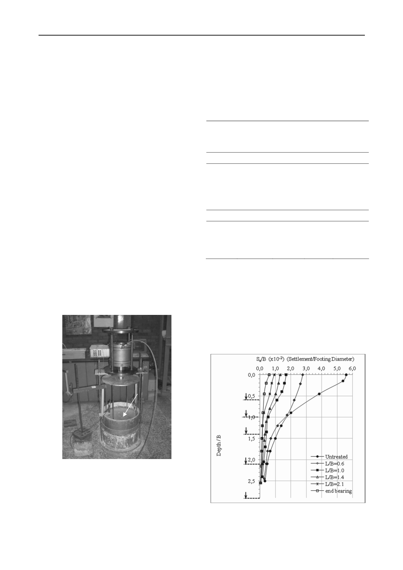
As seen in Figure 2 and Figure 3, cumulative displacements
occurring within the clay layer underneath column decrease
significantly in the columns longer than L/B=1.0.
Air jack
Frame
Loading Plate
end of column
(B=410 mm)
L/B=0.6
LVDT
L/B=1.0
Loading Tank
L/B=1.4
L/B=2.1
L/B=2.9 (eb)
Figure 2. Normalized settlement versus normalized depth graphs of
Series I and III (B = 100 mm, 75 kPa)


