964
Proceedings of the 18
th
International Conference on Soil Mechanics and Geotechnical Engineering, Paris 2013
normal stress increased degradation of the asperities is
associated with decrease in increase of the shear strength and at
very high normal stress the complete shearing of the asperity
takes place and there is no effect of boundary conditions on
shear strength.
II. The % increase in shear strength
of unfilled joint
under
CNS
conditions as compared to CNL conditions is as
high as
221
for P
i
=0.10 MPa
.
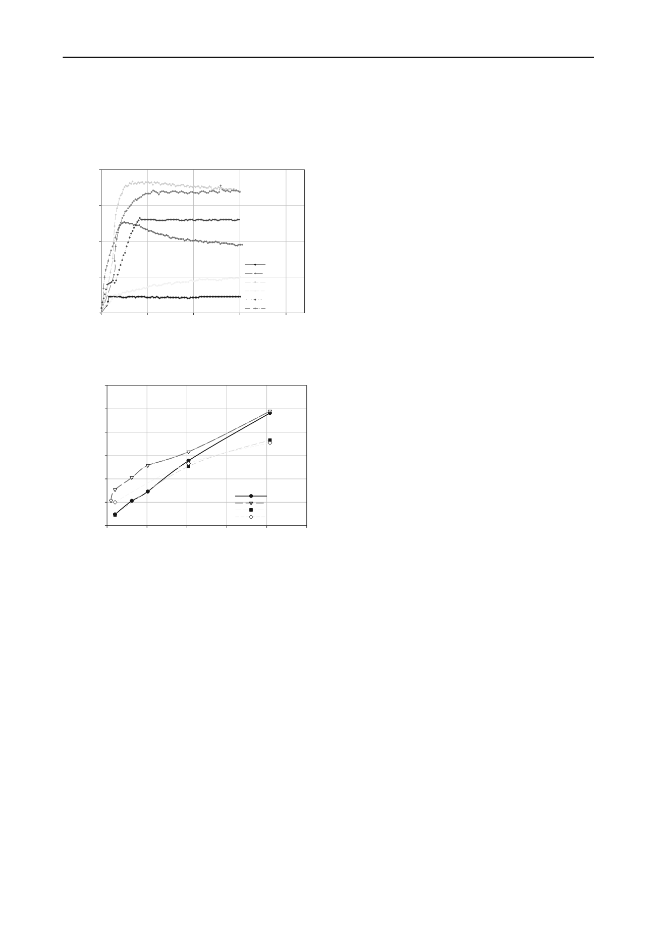
Shear Displacement (mm)
0
5
10
15
20
Shear Stress (MPa)
0.0
0.5
1.0
1.5
2.0
CNL, P
i
=0.10
CNL, P
i
=1.02
CNL, P
i
=2.04
CNS, P
i
=0.10
CNS, P
i
=1.02
CNS, P
i
=2.04
MPa
CNL, k
n
=0 kN/m
CNS, k
n
=8 kN/m
m
m
i
III. The effect of the infill material in the joint is to reduce
the shear strength and a maximum reduction of 35% is
observed for 5mm infill thickness under CNS conditions
at P =0.10 MPa.
IV. The effect of boundary conditions on the shear strength
of non planar unfilled/ infilled rock joints decreases with
increase in P
i
, the effect is almost nil for P
i
≥0.18σ
c
.
5 REFRENCES
Shrivastava A.K. and Rao K.S. 2009. Shear behaviour of jointed rock:
a state of art.
IGC-Guntur
, 245-249.
Patton F.D. 1966. Multiple modes of shear failure in rock and related
materials.
PhD Thesis
, University of Illinois, Urbana.
Barton N 1973. Review of a new shear strength criterion for rock
joints.
Engineering Geology
7, 287–332.
Barton N. 1976. The shear strength of rock and rock joints.
Int. J.
Rock Mech. Min. Sci. and Geomech. Abst.
13, 255-279.
Yang Z.Y. and Chiang D.Y. 2000. An experimental study on the
progressive shear behaviour of rock joints with tooth-shaped
asperities.
Int. J. Rock Mech. Min. Sci.
37, 1247–1259.
Figure 4. Shear behaviour of 15
0
-15
0
infilled joint under CNL and CNS
boundary condition.
Obert L., Brady B.T. and Schmechel F.W. 1976. The effect of normal
stiffness on the shear resistance of rock.
Rock Mech
. 8, 57-72.
Ooi L.H. and Carter P.J. 1987. A constant normal stiffness direct shear
device for static and cyclic loading.
Geotechnical Testing Journal
10, 3-12.
Initial Normal Stress (MPa)
0.0
0.5
1.0
1.5
2.0
2.5
Peak Shear Stress (MPa)
0.0
0.5
1.0
1.5
2.0
2.5
3.0
CNL unfill
CNS unfill
CNL infill
CNS infill
Johnston I.W., Lam T.S.K. and Williams A.F.1987. Constant normal
stiffness direct shear testing for socketed pile design in weak rock.
Geotechnique
37, 83-89.
Indraratna B., Haque A. and Aziz N. 1998. Laboratory modelling of
shear behaviour of soft joints under constant normal stiffness
condition.
J. Geotechnical and Geological Engineering
16, 17-44.
Gu X. F., Seidel J. P. and Haberfield C. M. 2003. Direct shear test of
sandstone- concrete joints.
Int. J. of Geomechanics
3, 21-33.
Kim D.Y., Chun B.S. and Yang J.S. 2006. Development of a direct
shear apparatus with rock joints and its verification tests.
Geotechnical Testing Journal
29, 1-9.
Kanji M.A. 1974. Unconventional laboratory tests for the
determination of the shear strength of soil-rock contacts,
Proc. 3
rd
Congr. Int. Soc. Rock Mech., Denver
2, 241-247.
ISRM 1977. Suggested method for determining water content,
porosity, density, absorption and related properties and swelling
and slake-durability index properties.
Figure 5. Strength envelope of 15
0
-15
0
unfilled and infilled joint under
CNL and CNS boundary condition.
ISRM 1979. Suggested method for determining the uniaxial
compressive strength and deformability of rock materials.
The increase in shear strength for unfilled joints for CNS
conditions varies from 221% to 6% of the CNL conditions
when P increases from 0.10 MPa to 2.04 MPa.
Deere D.U. and Miller R.P. 1966. Engineering classification and index
properties of rock,
Technical Report No. AFNL-TR-65-116
,
Albuquerque, N.M : Air Force Weapons Laboratory
.
i
The curvilinear strength envelope for infilled joint is
observed as presented in Fig.5 at all range of P
i
. But peak shear
stress of the infill joint is always less than that of unfilled joint.
Maximum reduction in shear strength of the infill joint as
compared to unfill joint for CNS condition is observed to be
35% at P
i
=0.01 MPa and % reduction in shear strength
decreases with increase in the P
i
. At high P
i
, the close look on
the sheared sample reflected breakage of the infill material,
which has resulted into more participation of the joints, hence
less reduction in shear strength.
Shrivastava A.K. 2012, Physical and Numerical Modelling of Shear
Behaviour of Jointed Rocks Under CNL and CNS Boundary
Conditions.
Ph.D. Thesis
, IIT Delhi.
Shrivastava A.K., Rao K.S. and Rathod, G.W. 2011. Shear
behaviour of infill joint under CNS boundary condition.
IGC - Cochi
, 981-984.
Rao, K.S., Shrivastava, A.K. and Singh Jattinder, 2009. Universal
large scale direct shear testing machine for rock.
INDOROCK- New
Delhi
, 157-168.
Shrivastava A.K. and Rao K.S. 2011. Shear behaviour of non
planar rock joints.
14
th
ARC on Soil Mechanics and
Geotechnical Engineering
, Hong Kong, China, 1-6.
4 CONCLUSIONS
The experimental studies on physically modeled unfilled and
infilled rock joints have been conducted to understand the effect
of boundary conditions and infill thickness on shear behavior.
The conclusions made from the test results are summarized
below:
I. CNL boundary condition is not suitable for non planar
rock joints and it under predict the shear strength, which
makes the design uneconomical.


