1770
Proceedings of the 18
th
International Conference on Soil Mechanics and Geotechnical Engineering, Paris 2013
3 MODEL TEST WITH CONSTANT WATER LEVEL
3.1
Test apparatus and conditions
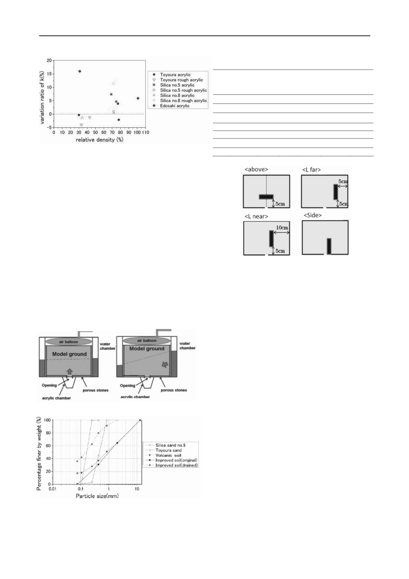
Test apparatus is schematically shown in Figure 3. This
apparatus is composed of three parts: center soil chamber, right
and left side water chambers. Porous stones were put between
the soil chamber and water chambers, and bottom plate of the
soil chamber. Through the porous stone, water was penetrated
freely. There was a 5mm width opening at the center of the
bottom plate of the soil chamber, which was closed initially. A
wooden block (2.1cm length, 10cm height, 8cm width) was put
into the ground with various positions, which simulated a buried
structure. It was painted and water penetration was prevented.
Positions of the block were shown in Figure 5. Overburden
weight was equivalent to the weight at 100cm deep of the
ground. Toyoura sand, silica sand no.5, improved soil and
volcanic soil were used. The improved soil was utilized at
construction site, and the volcanic sand caused a sinkhole
accident Particle size distributions of tested materials are shown
in Figure 4. All test cases are shown in Table 1.
3.2
Test procedure
The model ground was compacted on around optimum water
content. Water was penetrated from the bottom porous stone
plate or side water chamber, until horizontal or inclined water
level was kept steadily. After the model ground became stable,
opening was released and then water and soil was flown out
from the opening
3.3
Test result
Position of the block changed the situation of the cavity
formation. Dotted line in Figure 6 represented the water level
just before the opening released. When water level was inclined
and water was flown from right to left as shown in Figure 7,
cavity was generated below the block but overall tendency of
the formation was similar as the case without the block. From
Figure 7, it was suggested that water was penetrated around the
block by putting blue ink to water.
Improved soil prevented soil outflow in dense condition but
a cavity was expanded in loose condition. Particle size
distribution of drained soil was investigated and the result was
shown in Figure 4. It was suggested that drained soil contained
much more fines than original material. The amount of fines in
drained soil of case InL was 50% of whole amount of fines in
the model ground, which proposed that fines flown out from
large area. Test results of horizontal water flow conditions were
shown in Table 1.
“
Ratio of soil loss” in Table 1 means ratio
of weight of soil loss to total dry weight of soil in the model
ground.
“
Elapsed time” in Table 1 means time which took to
achieve the specified water level (10cm) which indicates
permeability. From Table 1, position of the block influenced not
on rise of water level but on soil outflow. On the other hand,
increasing of water level was very rapid in volcanic soil which
didn’t cause soil outflow. Loose condition of improved soil
caused much more rapid rise of water level than dense condition
of that which suggested the risk of soil outflow in large
hydraulic gradient.
Code Material
Position
of the
block
Dc or
Dr
(%)
Water
level(cm)
Ratio of
soil
outflow(%)
Elapsed
time
(sec)
Sn Silica no.5 None Dr 80
7.5
7.8
---
Tf
Toyoura
L far Dr 80
10
15.4 220
Ta Toyoura
Above Dr 80
10
7.1 220
Ts Toyoura
Side Dr 80
10
11.5 270
Vn Volcanic None Dr 80
10
0 150
InD Improved None Dc 90
10
0 340
InL Improved None Dc 75
10
0.4 150
Table 1. Test conditions with Constant & Horizontal water flow condition
Figure 2. Effect of cylinder’s small shaking on permeability
Figure 5. Positions of the block
Figure3
.
Schematically figure of the soil chamber with constant water
level
<Inclined >
<Horizontal
>
Figure
4. Particle size distribution


