1761
Technical Committee 204 /
Comité technique 204
Proceedings of the 18
th
International Conference on Soil Mechanics and Geotechnical Engineering, Paris 2013
sch
by 2 m work segments.
ually.
ments of existing footings, exceeding the 10 mm admissible
value.
It was decided not to take into account existing piles made in
2005. This decision was based on two facts.
Firstly, the static load tests on existing piles showed great
scatter in results. In fact, bearing capacity was two times lower
then its design. Secondly, the connection of reinforced concrete
capping beam to existing foundation made of crushed stone was
questionable. Assesment of existing foundation and its structural
integrity confirmed that the major part of the building load still
transfered through existing strip foundation despite the presence
of underpining piles.
With regard to aforementioned facts, a decision was made to
cancel piling from the analyses to ensure a safety margin.
There were considered various trench retaining options: root
piles, pressed-in piles, subsoil stabilization that could be techni-
cally possible in congested basement premises. However, none
of the existing methods could resolve the above issues and en-
sure an adequate safety margin. Fast fabricated root piles usually
have technological settlements unacceptable for the building in
question. Pressed-in piles, having no such disadvantage, were
used for the Bolshoi Theater refurbishment project, but they
proved to be very labor intensive, and their installation
required much more time than the time, remaining before
the P.I. Tchaikovsky Competition. Subsoil stabilization is not a
sufficiently safe solution, as in such soils it was difficult to en-
sure adequate quality of respective construction operations.
In view of all above mentioned circumstances a decision
was made to support 4.0...4.5 m ducts with root piles, reinforced
with steel pipes.
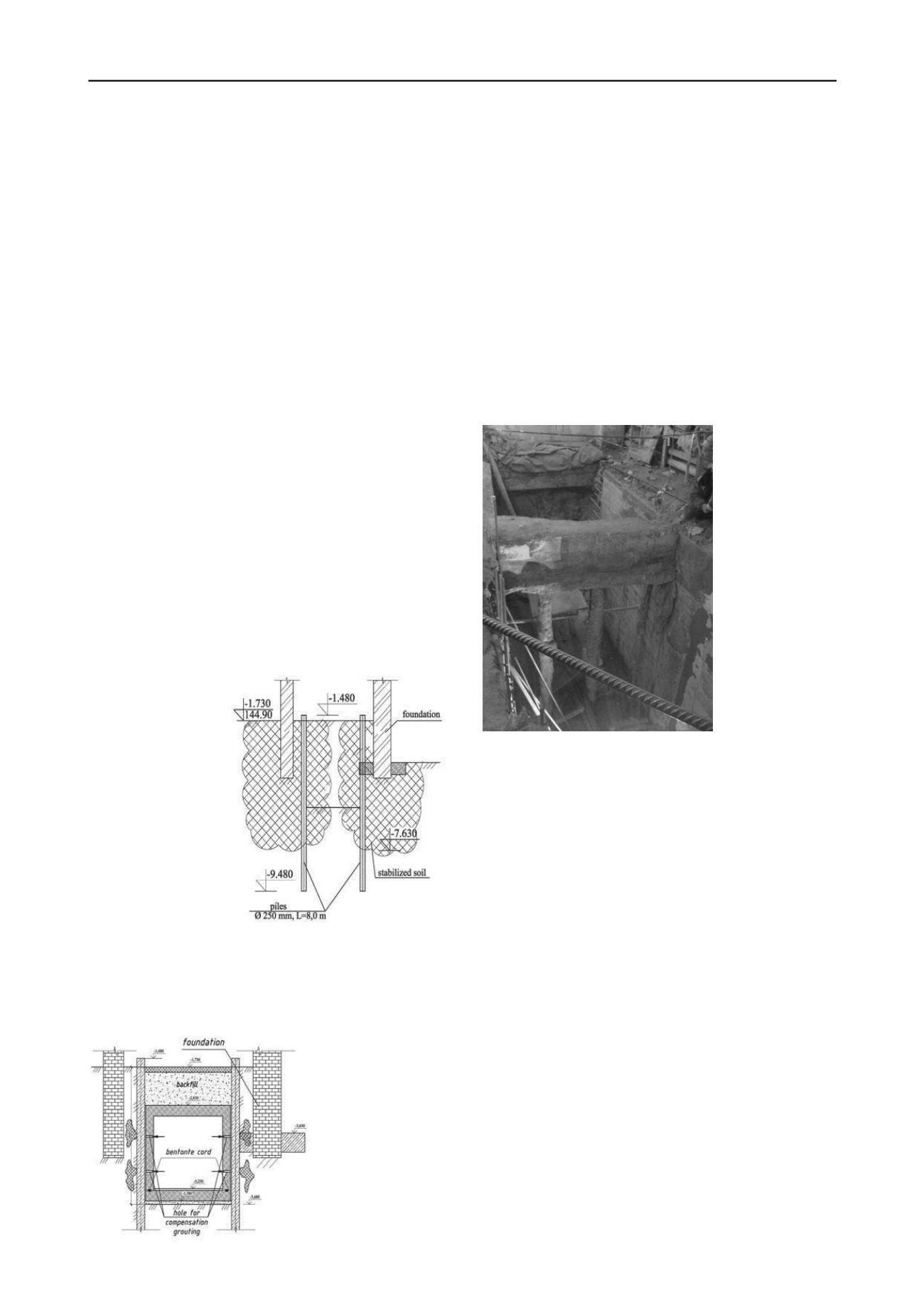
Realization of the project required a technique and a se-
quence of the underground operations, which would minimize
the construction the
impact of construc-
tion works on the
building
structure
(Petruknin V.P. et al.
2011). At the initial
stage the soil was
grouted with Micro-
dur suspension, then
the supporting root
piles were erected
(Figure 6), followed
by stagewise soil
excavation to design
depths and raft con-
creting, only then the
duct walls and the
floor were erected.
Figure 6. Soil stabilization layout and retaining piling
The reafter, in order to change the subsoil stress and strain
behavior multiple compensation grouting was done behind the
trench lining (Figure
7). Geodetic monitor-
ing of the footing
settlements showed
that the resulting
upheaval of markers
was up to 2…3 mm.
Figure 7. Duct concret-
ing layout with the com-
pensation grouting
eme
As is known the root piles’ advantage is their low cost and
fast erection, the only drawback is the respective technological
settlements of footings, which can be as much as several centi-
meters (Shulyatjev O.A. et al, 2008; Petrukhin V.P. et al, 2008).
In order to exclude technological settlements due to root piling
there were performed tests, and a drilling set-up was developed,
protected by a RF patent (Petrukhin V.P., Popsuenko I.K., Shu-
lyatjev O.A., 2011), that compensated soil stress-strain behavior
variation due to drilling by stagewise vertical pressurizing to-
gether with filling the bore hole with cement-sand grout, whose
composition excluded sedimentation. The operations were per-
formed gradually
According to the above mentioned patent the hole drilling
was accompanied by compaction and hole walls troweling to
prevent water-saturated liquefied soil falling in the borehole.
Figure 8 shows a photograph of a duct segment under the Big
Hall, dug out manually to the design depth.
At the fore-
front root piles,
made in 2005, are
visible, they are
joined together by
a concrete raft, they
are a sort of struts.
Soil
excavation
from ducts is a
rather
labor-
intensive process,
therefore, as di-
mensions of the
premises
were
small, the soil was
dug out man
Figure 8. 4.5 m deep service duct
In order to reduce footings settlements during ducts mining
operations the soil under bearing walls was grouted with “Mi-
crodur” suspension.
Therefore, the subsequent soil excavation showed that soil
stabilization had been done adequately, however, practically no
traces of grouting were discovered at some points in spite of the
customer permanent strict control and designer supervision.
Thus, it indirectly proved that the safer selected option i.e., re-
taining piles, was correct.
Soil mining under bearing walls of the building was a com-
plicated issue. As is mentioned above, it is wrong during soil
mining to rely on earlier arranged root piling. Therefore, a steel
frame set-up was elaborated for 4,5 m deep ducts, which sup-
ported a part of the wall, under which the soil was dug out.
Mining 1,8 deep ducts was even more difficult. Notably,
shallow ducts mining was performed not only in soil, it was
often done along the body of rabble stone footing (the footing
width was up to 1,5 m), therefore, soil excavation looked as
non-mechanized mining (all operations were manual).
Underground development project involved various geo-
technical operations that required on-line integrated geotechnical
monitoring, performed by a specialized company in the most
optimal way. Moreover, the designer company (Gersevanov
NIIOSP) carried out their own supervision of the vertical and
lateral displacements of the footings and of the Conservatory
building structure. The congested conditions of the refurbish-
ment operations, numerous labor force, multiple material stor-
age sites, etc. restricted installation of an up-to-date on-line set-


