1764
Proceedings of the 18
th
International Conference on Soil Mechanics and Geotechnical Engineering, Paris 2013
Figure 1. Stratigraphic section of the zone where atypical deformations
were observed (1+000).
Cracking. Because the channel was built excavating the land, it
is considered a zone of unloading. During construction of the
tunnel’s shafts near the channel, the presence of subsoil
cracking has been observed. In order to verify the existence of
that unloading zone, and the presence of developed cracking
given the low value of the shear resistance factor for Valley of
Mexico clay (
K
IC
≈1.9t/m
3/2
), the
k
o
stress ratio at rest was
determined at the site, and an exploration campaign was carried
out with piezocones in zones near to and far from the channel.
The stress ratio at rest for the superior clayey series was
k
0
=0.19
for the zone near the channel, whereas at the zone away from
the channel the value was
k
0
=0.6. It is to be pointed out that the
low
k
0
value measured for the superior clayey series at the
channel zone is evidence of the state of decompression due to
the channel’s influence, and vertical cracking presented by the
superior clayey formation. One way of observing cracking on
clayey soils is to measure point resistance and friction of the
electric cone, because when a discontinuity crosses, the values
of such resistance decrease. When comparing electric cone
point resistances in soundings carried out near to and far from
the channel, resistances are observed to descend at certain
depths in the case of the cone near the channel, a condition not
present in the far-away cone (Fig 2).
0
5
10
15
20
25
30
0
2
4
6
8
10
Conebearingcapacityq
c
(kg/cm
2
)
Depth(m)
Away from the channel
Near from the channel
Figure 2. Soundings of piezocones carried out at the channel’s zone of
influence and away from it.
3 INSTRUMENTATION AND BEHAVIOR
The tunnel’s instrumentation consisted of placing piezometers,
bar extensometers, doing convergence measurements at the ring
sections, and pressure cells at the point of contact between soil
and primary lining (COMISSA 2011).
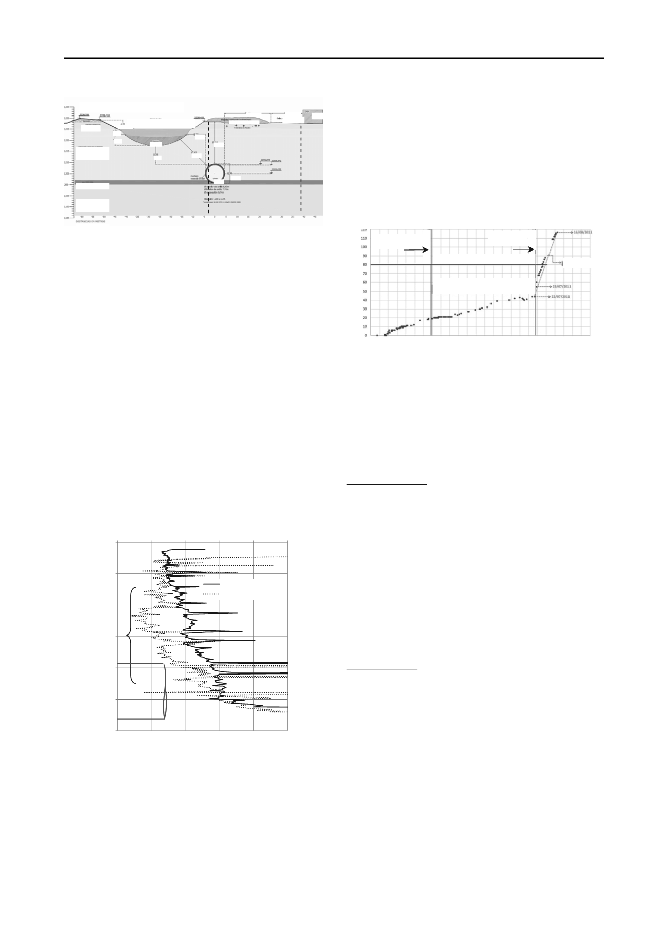
In general, the tunnel’s behavior during construction
coincides with those determined at the design stage, meaning
that the displacements of the primary lining were in the order of
40mm, with top measurements of 60mm (80mm is the value of
1% of the tunnel’s diameter). Nonetheless, prior construction of
the secondary lining, and once the primary lining’s stabilization
was reached, with deformation speeds below 1 mm/day, and
after the reinjection at the point of contact of lining and soil
along the section built, a sudden increase in convergences was
observed at the tunnel section 0+920 to 1+032 (rings 610 to
730), which is attributable to various extraordinary events that
occurred at the tunnel’s environment, which induced a change
in the original geotechnical conditions. This event coincided
with channel dredging activities, as observed on the
convergence graphs of the rings located at that zone (Fig 3).
Figure 3. Example of deformational behavior at zone with important
displacements (ring 671).
4 NUMERICAL MODELING
In order to assess the unloading effect at surface and the
fracturing present at the superior clayey series, a bi-dimensional
analysis was carried out with the Finite Element Method. In this
analysis, the soil’s fracturing is represented by a decrease of the
clay’s mechanical properties.
Analysis procedure. Taking the soil parameters registered on
site as reference, the topographical section of the tunnel showed
in Fig 1 was considered for the analysis and study of the
tunnel’s behavior, reproducing the initial geotechnical
conditions, modified by the soil’s fracturing, and the effect of
the channel dredging activities. 2D numerical analysis was done
in stages, the following being the main ones:
i. Evaluation of geostatic stress conditions
ii. Construction of the channel and placement of the borders
iii. Excavation and placement of the tunnel’s primary lining
iv. Change of subsoil properties, induced by fracturing
v. Land consolidation by the decrease of pore pressure at a 6
month interval
vi. Channel dredging inducing variable unloading between 85
and 97kN/m
2
vii. Decrease of groundwater level of 1 m.
Numerical model. The finite elements mesh shown in Fig 4 was
used, with the mechanical properties indicated in it. An
important hypothesis considered in the analysis is to admit that
both the tunnel’s construction and the channel dredging process
are produced under undrained conditions of the soil. In effect,
taking into account the time during which the deformation
develops, it is adequate to consider that this subsoil behavior is
under undrained conditions. The only stage in which the
undrained behavior is not considered is the one produced by the
consolidations over 6 months.
5 RESULTS
A numerical analyses were carried out in order to determine the
state of stresses and deformations at each stage of analysis both
in the subsoil and in the lining, with or without considering
subsoil cracking.
Table 1 shows the results obtained at each stage of analysis.
The displacement obtained when the soil presents no fracturing
4.07
Distance (m)
PZC 2
PZC 1
Freatic level
House
Street
Dredgingmaterial
Superior
clayed series
Hard layer
Inferior
clayed series
21.12
14.14
Crust
8.3
17.6
8.3
19.2
8.24
Tunnel
MUD
5
2.6
Change of
behavior
Cracking zone
3 months of stable period of
deformation
1% of the diametral deformation
Begining of the
linning stability
Deformation mm
V=2.2mm/day
Time (weeks)
0
5
10
15
20


