 
          1771
        
        
          Technical Committee 204 /


            Comité technique 204


            Table 2. Test conditions with Repetition of water penetration


          4 MODEL TEST WITH REPETITION OF WATER
        
        
          PENETRATION
        
        
          4.1


            Test apparatus and conditions


          Test apparatus was composed only of the center soil chamber.
        
        
          This soil chamber size is 30cm long, 20cm high, 5cm wide. It
        
        
          has the 5mm width opening at the center of the bottom plate and
        
        
          soil was drained from there. Two patterns of water supply point:
        
        
          “Opening” and “Side wall”, were set as presented in Figure 8.
        
        
          Overburden weight was equivalent to the weight at 100cm deep
        
        
          of the ground. A wooden block (2.1cm length, 10cm height,
        
        
          5cm width) was set into the ground with 4 kinds of the
        
        
          position.(as shown in Figure 4) Toyoura sand was used and
        
        
          particle size distribution was shown in Figure . In Lfar test case,
        
        
          colored sand layer was made in every 3cm thickness. Table 2
        
        
          was shown the test conditions.
        
        
          4.2


            Test procedure


          Model ground was compacted on around 10% water content.
        
        
          Approximately 100cc water was supplied with head difference
        
        
          of 100cm. Water supply cycle was repeated until the cavity
        
        
          reach ground surface.
        
        
          4.3


            Test Result


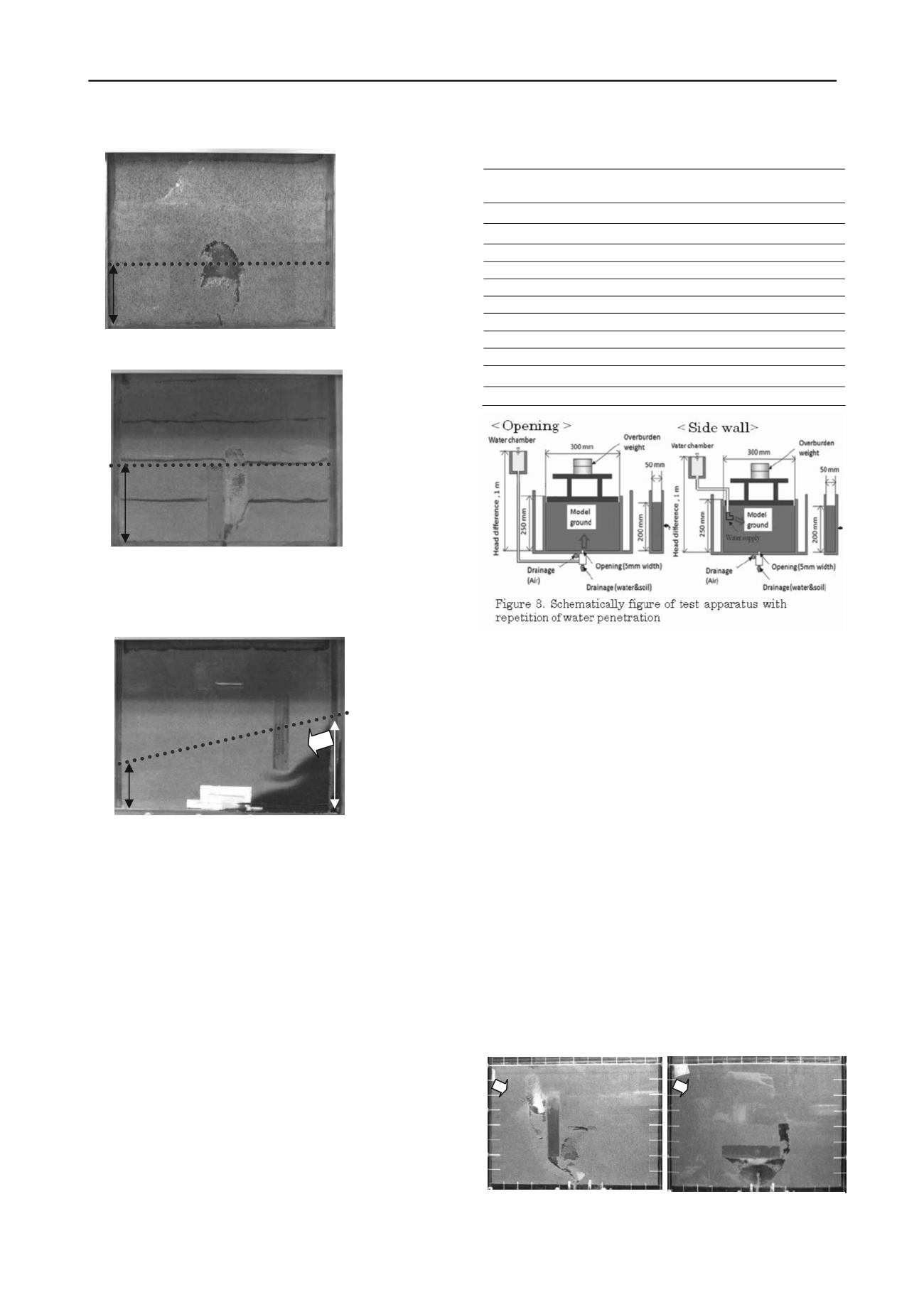
          Cavity formations of TSwne and TSwa are shown in Figure 9.
        
        
          Arrow signified the direction of water supply. If water was
        
        
          supplied from horizontal direction, cavity was generated around
        
        
          the block. In TSwf test case, water content was measured at
        
        
          several points as shown in Figure 10. Figure 10 suggested water
        
        
          content was not uniform in the model ground. It was supposed
        
        
          that water flew from water supply to the opening and passed
        
        
          through the right side of the block.
        
        
          Dry weight of drained soil was measured in each cycle, and
        
        
          ratio of cumulative soil loss to total weight of soil in the model
        
        
          ground was calculated. Rapid soil loss was observed in the test
        
        
          case which the block didn’t disturb water flow (such as TOps
        
        
          and TOpa cases). Although the cavity expansion was stopped
        
        
          after a certain cycle in the test case without the block because
        
        
          amount of water is not enough for reaching to the top of the
        
        
          cavity and breaking the arching of the ground, it didn’t stop in
        
        
          that with the block. Ground arching around a cavity was
        
        
          disturbed by the block and water pathway was generated. Total
        
        
          Code
        
        
          Material Position of the
        
        
          block
        
        
          Initial Water
        
        
          content (%) Dr (%)
        
        
          TOpn Toyoura
        
        
          None
        
        
          10 Dr 80
        
        
          TOpf
        
        
          Toyoura
        
        
          L far
        
        
          10 Dr 80
        
        
          TOpne Toyoura
        
        
          Lnear
        
        
          10 Dr 80
        
        
          TOpa
        
        
          Toyoura
        
        
          above
        
        
          10 Dr 80
        
        
          TOps
        
        
          Toyoura
        
        
          side
        
        
          10
        
        
          Dr80
        
        
          SiOps
        
        
          Silica no.5
        
        
          sude
        
        
          10
        
        
          Dr80
        
        
          SiOpn Silica no.5
        
        
          None
        
        
          10
        
        
          Dr80
        
        
          TSwf
        
        
          Toyoura
        
        
          Lfar
        
        
          10
        
        
          Dr80
        
        
          TSwne
        
        
          Toyoura
        
        
          Lnear
        
        
          10
        
        
          Dr80
        
        
          TSwa
        
        
          Toyoura
        
        
          above
        
        
          10
        
        
          Dr80
        
        
          TSws
        
        
          Toyoura
        
        
          side
        
        
          10
        
        
          Dr80
        
        
          7.5CM
        
        
          A) Sn, w
        
        
          initial
        
        
          =10%
        
        
          Figure 9. Cavity formation with repetition of water penetration
        
        
          b) TSwa, 7
        
        
          th
        
        
          water supply
        
        
          a) TSwne, 7
        
        
          th
        
        
          water supply
        
        
          Figure 6. Cavity formation of the model test
        
        
          with horizontal water level
        
        
          10 CM
        
        
          B) Ts, w
        
        
          initial
        
        
          =10%,
        
        
          12 CM
        
        
          7 CM
        
        
          TOYOURA SAND, DR=80%, W
        
        
          i
        
        
          =10%, Lfar,
        
        
          Water level L:7cm R:12cm
        
        
          Figure 7. Water penetration around the block with inclined
        
        
          water level