1760
Proceedings of the 18
th
International Conference on Soil Mechanics and Geotechnical Engineering, Paris 2013
Proceedings of the 18
th
International Conference on Soil Mechanics and Geotechnical Engineering, Paris 2013
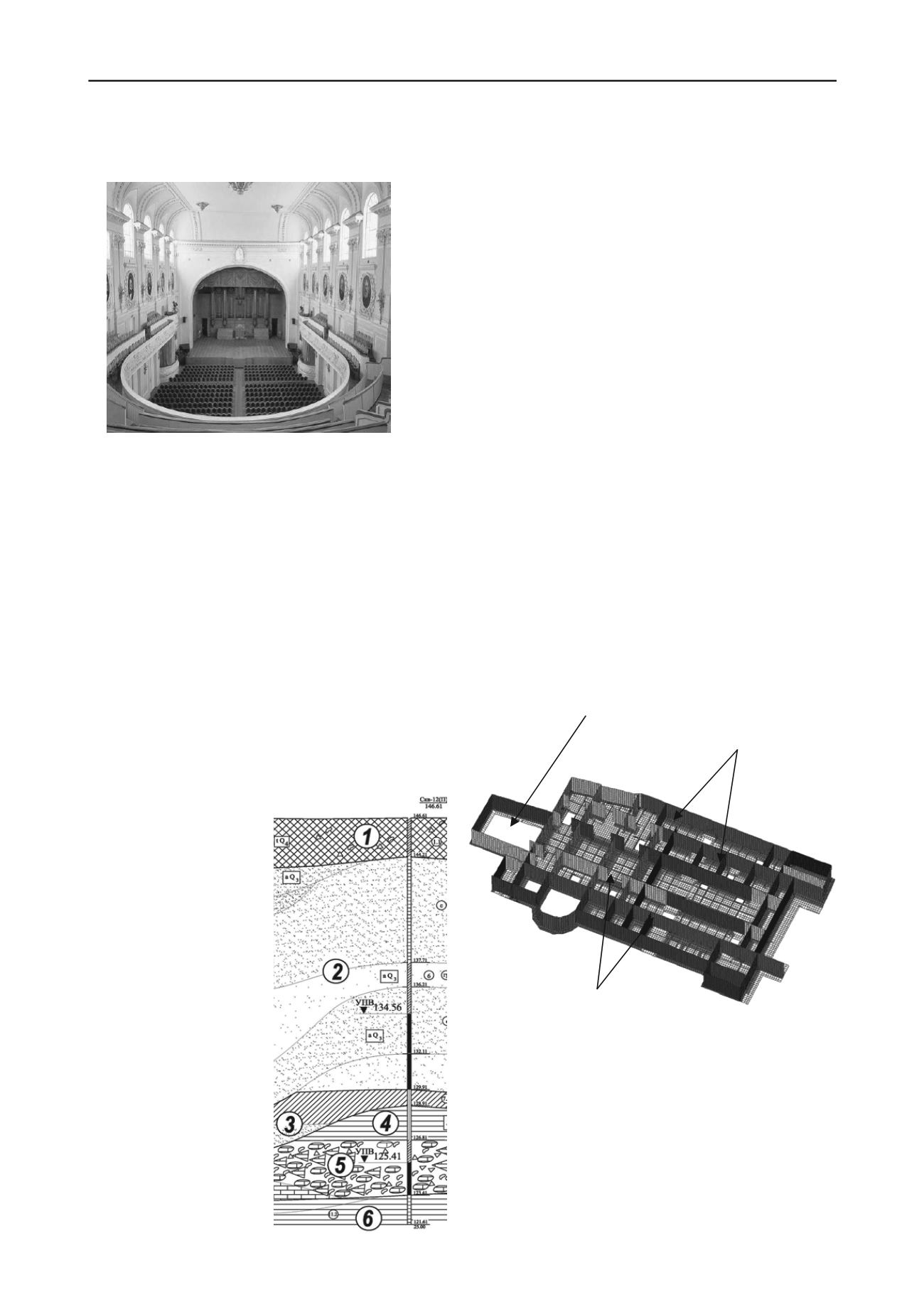
the refurbishment and restoration activities in the Big Hall (Fig-
ure 3) and in the lobbies were practically completed.
Figure 3. Conservatory Big Hall after refurbishment
This largely complicated the underground work below the
building, because even negligible footing settlements during
geotechnical operations could generate cracks in the structures
and to destroy decorations and restorations, since long-term
monitoring of the Conservatory building structural health
prompted that 10 mm footings settlements would generate
cracks in the superstructure parts.
In view of the foregoing, the design solutions for the under-
ground portion of the Moscow P.I. Tchaikovsky Conservatory
were developed that accounted for the following requirements of
the technical assignment:
- underground development operations below the Conser-
vatory building, including the Big Hall premises, were to be
performed to 4,5 m depth below the basement floor, i.e. 3,5 m
below the footings;
- 6 months deadline for the underground space development
was assigned;
- extra settlements of the Conservatory building footings
should not exceed 10 mm.
The geological section
includes contemporary, upper
and mid-Quaternary deposits
as well as Upper Jurassic and
Upper Carbon deposits (Fig-
ure 4).
Contemporary deposits –
antropogenic soils (1), repre-
sented by a mixture of sand-
sandy loam-clay loam soils,
compacted
and
not-
compacted, with low moisture
content
and
moistened
0,8…4,6 m thick. They are
underlain by Upper Quater-
nary alluvial deposits (2),
represented by sands of vari-
ous grain-size composition
and loose (in the lower part
of the section), with low and
high moisture content and
water-saturated 6,0…14,3 m
thick.
Figure 4. Geological section
Below Mid-Quaternary deposits, there were discovered flu-
vioglacial deposits (3) 4,8 m maximal thick, represented by
sands and sandy loams. The sands are fine-grained of medium
density, water-saturated, sandy clay loams are high to low plas-
tic. Below there occur Upper Jurassic of Oxford tiers (4), repre-
sented by silty low-plastic clays. The bed maximum thickness is
7,6
a low-strength limestone bed, moistened
and
at 24,35-25,5 m depth. The terrain is naturally water-
log
nfavorable processes and events were found on the ter-
rain
t of service ducts
wit
ining structures.
Internal courtyard
ep ducts
servatory underground model with 1.8 and 4.5 m deep
service ducts
ported excavation of duct trenches would cause to extra settle-
-7,8 m.
Deeper below Upper Carbonic deposits were found, repre-
sented by up to 3,4 m thick bed of Izmailovskyi limestone (5),
crushed to powder or gravel; Mescherinskaya 3.3-6.0 m thick
bed (6), represented by dusty low-plastic, medium hard and hard
clays; Perkhurovskay
water-saturated.
In terms of hydrogeology the terrain is characterized by oc-
currence of three aquifers: phreatic, Super Jurassic at 5,0-15,7
m below the surface; Izmailovsky at 14,5-21,36 m depth; Perk-
hurovsky
ged.
The surveyed terrain features no karst or washout risk. No
other u
.
Investigation of soil stress and strain behavior was numeri-
cally simulated, using FEM and non-linear soil models in
PLAXIS 2D for a characteristic section along ducts 1,0…4,5 m
deep. 3D analysis of structures was made with the help of Mi-
croFe 2008 software (Figure 5). The analysis covered all work
stages from soil stabilization to soil excavation down to design
depths. Based on technological and architectural requirements as
well as on structures’ strength, stability and crack resistance in
interaction of subsoil with the Conservatory building there were
established the ultimate values of joint deformations equal to 10
mm. Prior to the project design development various options
were analyzed that would enable arrangemen
hout auxiliary reta
4.5 m de
1.8 m deep ducts
Figure 5. Con
The analyses demonstrated that in such geological condi-
tions 1,8 m deep ducts would hold with no support if they are
strengthened with piles. But in order to exclude extra settle-
ments of existing footings due to subsoil softening and walls
caving, which could not be simulated in the analysis, there was
designed and implemented multiple (up to 5 times) cement mor-
tar compensation grouting behind the concrete walls in accor-
dance with the method, developed by NIIOSP (Shulyatjev O.A.
et al, 2008). The analysis showed that 4,0…4,5 m deep unsup-


