1546
Proceedings of the 18
th
International Conference on Soil Mechanics and Geotechnical Engineering, Paris 2013
column maintains stable during the earthquake since no
liquefaction leads to the loss of bearing capacity.
3.3
Influence of the soil properties of the surface layer
In this section, the effect of the sequence of ground layers on
the seismic stability of the steel fabricated column is
investigated assuming a weak clay soil layer interposed below
the liquefiable layer. Two cases are investigated, one with a
thickness of the sandy soil surface layer above the weak clay of
12 m (Case4) and one with a thickness of 3 m (Case5). The
depth of embedment concrete of the column is 2m in each case.
The ground conditions involved in this section will be classified
as same category based on microtopography classification
method which pays attention only to the surface ground.
Fig. 11 shows a comparison of the deformation (horizontal
displacements and vertical settlements) at the tips of the
column. It can be seen that even though the soil of the surface
layer is the same, the stability of the structure varies greatly
depending on the differences in stratigraphic composition and
thickness of the surface layer. In other words, in Case1, which
consists of sand layers only, the oscillations during the
earthquake are small and a residual horizontal displacement of
only 15cm (1.0% of inclination) is ultimately reached in the
structure. However, in Case4, where the clay layers are covered
by a liquefiable layer, the oscillations during the earthquake are
larger compared with Case1, and the residual horizontal
displacement increases to 24cm (1.6% of inclination), which
means the stability is reduced. Moreover, in Case5, where the
thickness of the liquefiable layer is small, the oscillations during
the earthquake are even greater, and the column topples over
during the earthquake.
0
50
100
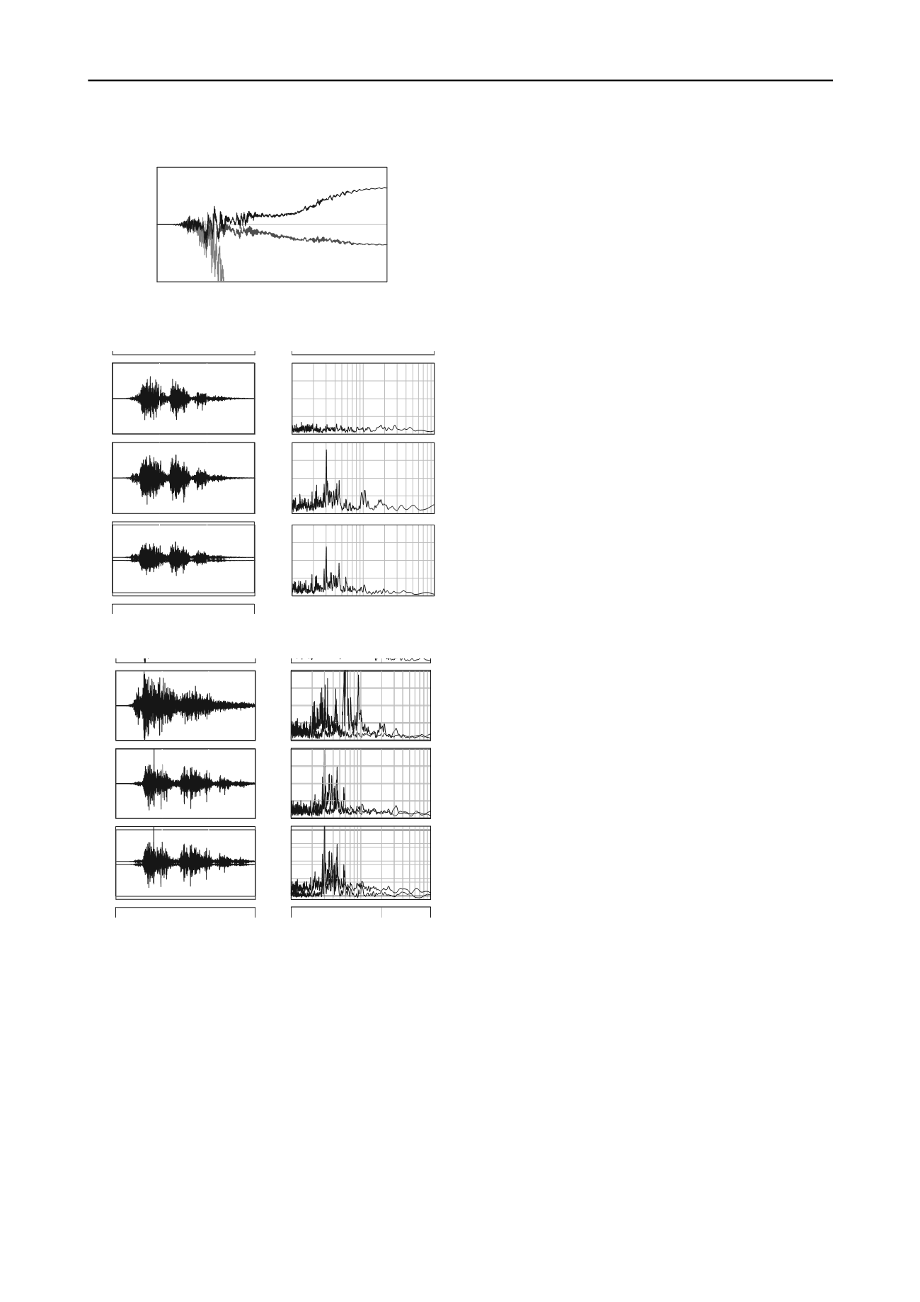
Figs. 12 and 13 present the acceleration response and the
Fourier amplitude spectrum at each layer boundary for Case4
and 5 respectively. When the clay layers are interposed below,
the acceleration is greatly amplified in the clay layers especially
in the long-period wave, and it can be regarded that there is an
increase in the input acceleration for the liquefiable surface
layer. Although once again, the acceleration is attenuated in the
liquefied layer, but at the case of thin liquefied layer, the
attenuation of acceleration is not so apparent that the structure
oscillates greatly.
From the above, it can be seen that even when the soil of
the surface layer on which the structure installed is same, the
seismic stability of the structure varies greatly depending on the
differences in the stratigraphic composition (sequence and
thickness of layers). In particular, when there is a thick deposit
of weak clay below a liquefiable layer and the thickness of a
liquefiable surface layer is small, the stability of the structure
above is significantly reduced.
150
40
20
0
- 20
- 40
Time (s)
Horizontal displacement (cm)
Case5
Case2
Case6
Figure 11.
Comparison of the deformation at the tips of the column for
Case2, 5 and 6
10
-1
10
0
10
1
0
100
200
300
400
0
100
200
300
400
0
100
200
300
400
0
Period (s)
4 CONCLUSIONS
In this paper, the seismic stability of steel fabricated column
constructed on liquefiable ground with different stratigraphic
composition of the deep layers was evaluated using
dynamic/static soil-water coupled finite deformation analysis
taking into consideration soil-structure interaction during the
earthquake.
Plastic deformation was predominant in the liquefied sand
layer, which led to a decrease in acceleration at the ground
surface. However, if the embedment depth was shallow with
high gravity center, the structure would still incline easily due to
the loss of bearing capacity by liquefaction in the subsurface
layer and gradually tilt under its own weight.
When there was a clay layer seated on the liquefiable layer,
the accelerations were amplified in the clay layer leading to an
increase of input acceleration for the liquefiable layer, and there
was a risk that the oscillations of the structure would be
increased. In particular, when the thickness of the liquefiable
layer was small, the attenuation of the acceleration in the
liquefiable layer was small, so the stability of the structure
above was significantly reduced.
5 REFERENCES
Asaoka et al. 2002. An elasto-plastic description of two distinct volume
change mechanisms of soils. S&F, 42 (5), 47-57.
Noda et al. 2008. Soil-water coupled finite deformation analysis based
on a rate-type equation of motion incorporating the SYS cam-clay
model. S&F, 48 (6), 771-790.
Noda et al. 2009. Co-seismic and post-seismic behavior of an alternately
layered sand-clay ground and embankment system accompanied by
soil disturbance, S&F, 49(5), 739-756.
Fourieramplitude (gal*s)
Fourieramplitude (gal*s) Fourieramplitude (gal*s) Fo
0
50
100
150
-800
0
800
-800
0
800
-800
0
800
-800
Time (s)
Acceleration (gal)
Acceleration (gal)
Acceleration (gal)
800
-800
0
800
A celeration (gal)
Ground surface
Boundary between
Ac & Fs
Boundary between
M & Ac
Ground surface
Boundary between
Ac & Fs
Boundary between
M & Ac
Figure 12. Acceleration response and the Fourier amplitude spectrum at
each layer boundary for ground Type C
10
-1
10
0
10
1
0
100
200
300
400
0
100
200
300
400
0
100
200
300
400
0
Period (s)
Fourieramplitude (gal*s)
Fourieramplitude (gal*s) Fourieramplitude (gal*s) Fo
400
0
100
200
300
400
300
300
4
l*s)
Fourieramplitude (gal*s)
u
itude a
itude a )
0
50
100
150
-800
0
800
-800
0
800
-800
0
800
-800
Time (s)
Acceleration (gal)
Acceleration (gal)
Acceleration (gal)
800
-800
0
800
A celeration (gal)
tion g l
e tion g l
Ground surface
Boundary between
Ds & Ac
Boundary between
M & Ds
Ground surfa
Boundary between
Ds & Ac
Boundary between
M & Ds
ce
Figure 13. Acceleration response and the Fourier amplitude spectrum at
each layer boundary for ground Type D


